SWRZ092B April 2021 – March 2022 IWR6843AOP
- 1Introduction
- 2Device Nomenclature
- 3Device Markings
- 4Usage Notes
- 5Advisory to Silicon Variant / Revision Map
-
6Known Design Exceptions to Functional
Specifications
- MSS#03
- MSS#10
- MSS#11
- MSS#12
- MSS#13
- MSS#14
- MSS#16
- MSS#17
- MSS#18
- MSS#19
- MSS#20
- MSS#21
- MSS#22
- MSS#23
- MSS#24
- MSS#25
- MSS#26
- MSS#27
- MSS#28
- MSS#29
- MSS#30
- MSS#31
- MSS#32
- MSS#33
- MSS#34
- MSS#35
- MSS#36
- MSS#37B
- MSS#38A
- MSS#39
- MSS#40
- MSS#41
- MSS#42A
- MSS#43A
- MSS#44A
- MSS#45
- 6.1 MSS#50
- 6.2 MSS#51
- ANA#11B
- ANA#12A
- ANA#13B
- ANA#14
- ANA#16
- ANA#17A
- ANA#18B
- ANA#19
- ANA#20
- ANA#22A
- 6.3 ANA#27A
- ANA#30
- ANA#31
- DSS#01
- DSS#02
- DSS#03
- DSS#05
- DSS#07
- PACKAGE#01
- PACKAGE#02
- 7Trademarks
- 8Revision History
MSS#35
EDMA TPTC Generates an Incorrect Address on the Read Interface, Causing one or More Data Integrity Failures, Hangs, or Extra Reads
Revision(s) Affected:
IWR6843AOP ES1.0 only
Description:
Certain scenarios could lead to an incorrect read, hang, or data integrity issues in the EDMA TPTC block. Table 6-1 shows the various scenarios and the resulting effects of each scenario.
A scenario happens, if ALL conditions listed for that scenario are satisfied (true); that is, "AND" of all conditions.
A “hang” outcome means that one or more attempts of the hang causing scenarios can progressively lead to not receiving a "transfer completion" indication from the TPTC. The last transfer attempt which does not receive the completion indication can be any transfer – any scenario transfer within this advisory or even outside of this advisory.
| SCENARIO ID |
CONDITIONS | DATA INTEGRITY FAILURES |
HANGS | EXTRA READS |
|---|---|---|---|---|
| 1 | AB-sync BCNT > 1 ACNT not in [2,4,8,16,32] (ACNT < 64) OR ((ACNT = 64) AND (SRCBIDX != ACNT)) Source Addressing crossing 4-KB boundary for any of the BCNT number of ACNT transfers. |
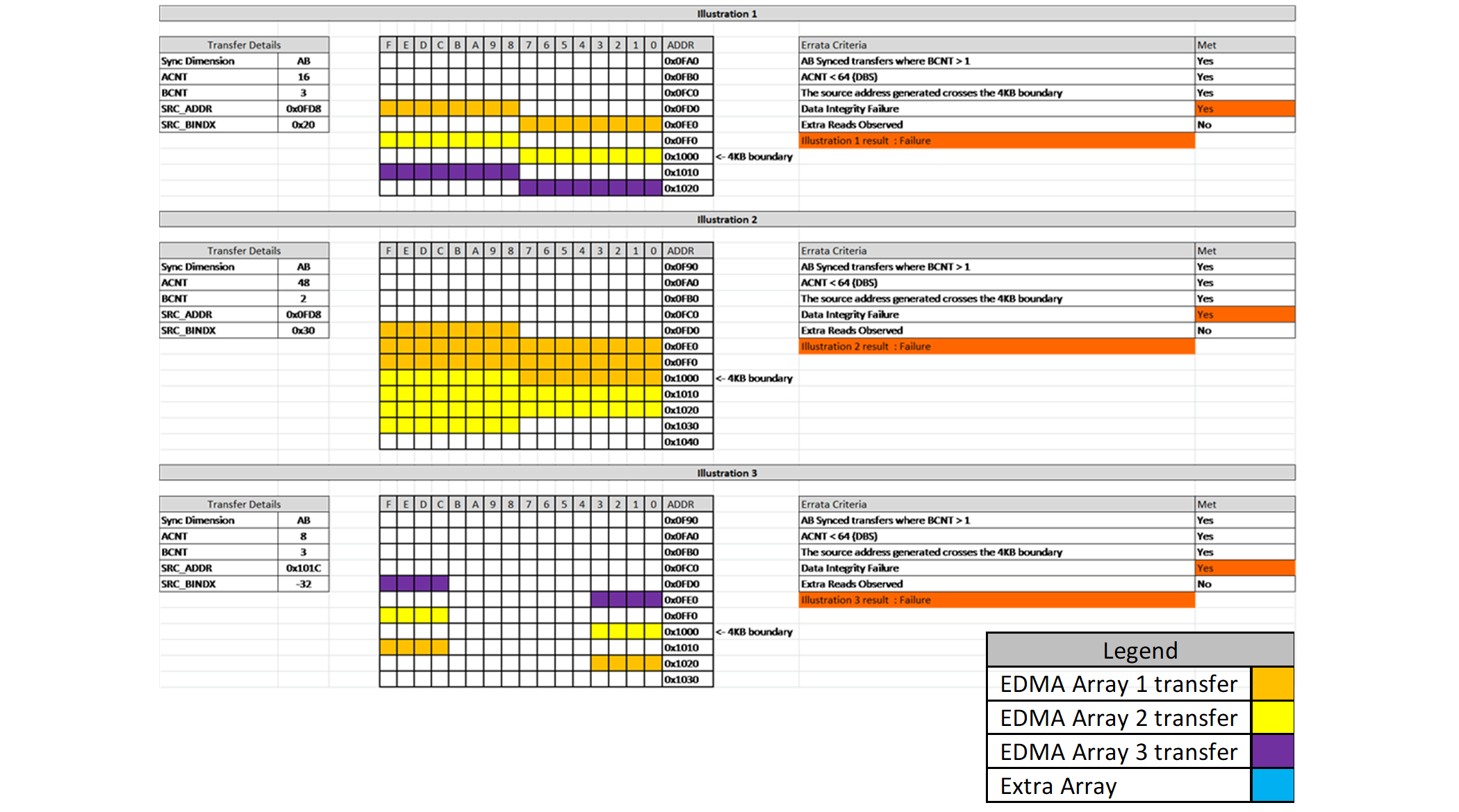
Yes (see Figure 6-4) |
Possible | Possible |
| 2 | AB-sync with BCNT=1 or A-sync ACNT not in [2..24, 32] ACNT <= 64 Source Addressing crossing 4-KB boundary for any of the BCNT number of ACNT transfers. |
No | Possible | Yes |
| 3 | AB-sync with BCNT=1 or A-sync ACNT in [2..24, 32] Source Addressing crossing 4-KB boundary for any of the BCNT number of ACNT transfers. |
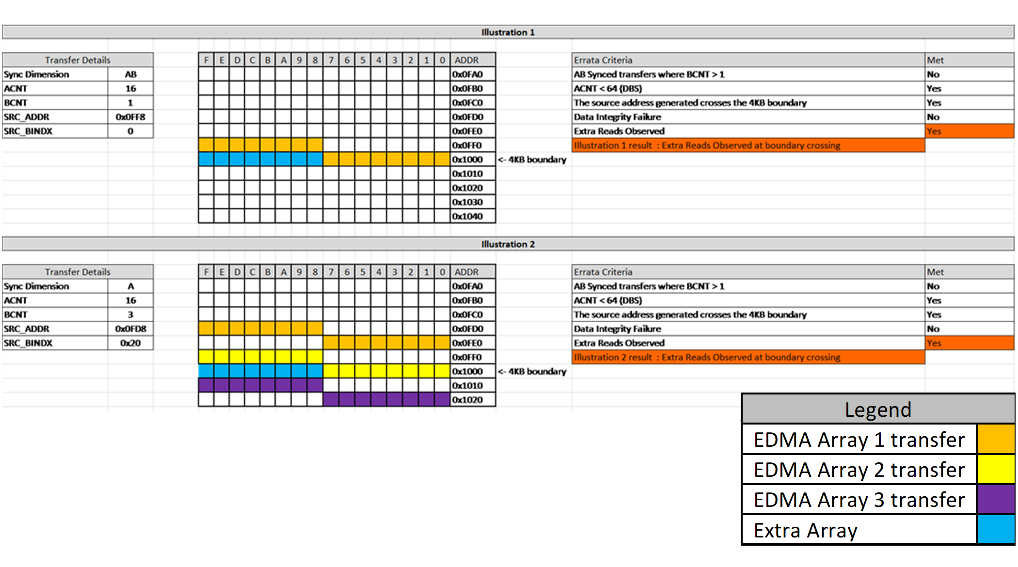
No | No | Yes (see Figure 6-1) |
| 4 | AB-sync BCNT > 1 ACNT in [2,4,8,16,32] SRCBIDX = ACNT ACNT * BCNT <=64 Source Addressing crossing 4-KB boundary for any of the BCNT number of ACNT transfers. |
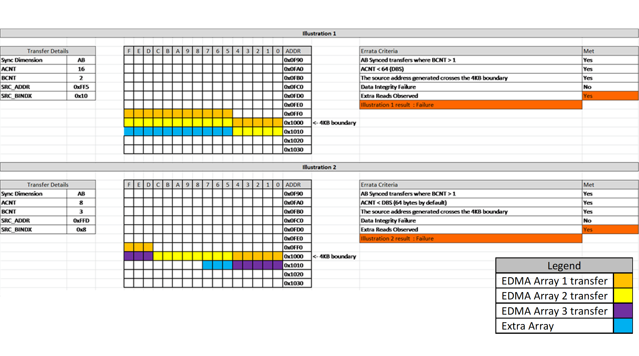
No | No | Yes (see Figure 6-2) |
| 5 | AB-sync BCNT > 1 ACNT in [2,4,8,16,32] SRCBIDX = ACNT ACNT * BCNT <=64 Source Addressing does NOT cross 4-KB boundary for any of the BCNT number of ACNT transfers; that is, NOT of Source Addressing crosses 4-KB boundary for merged source array of size ACNT * BCNT. |
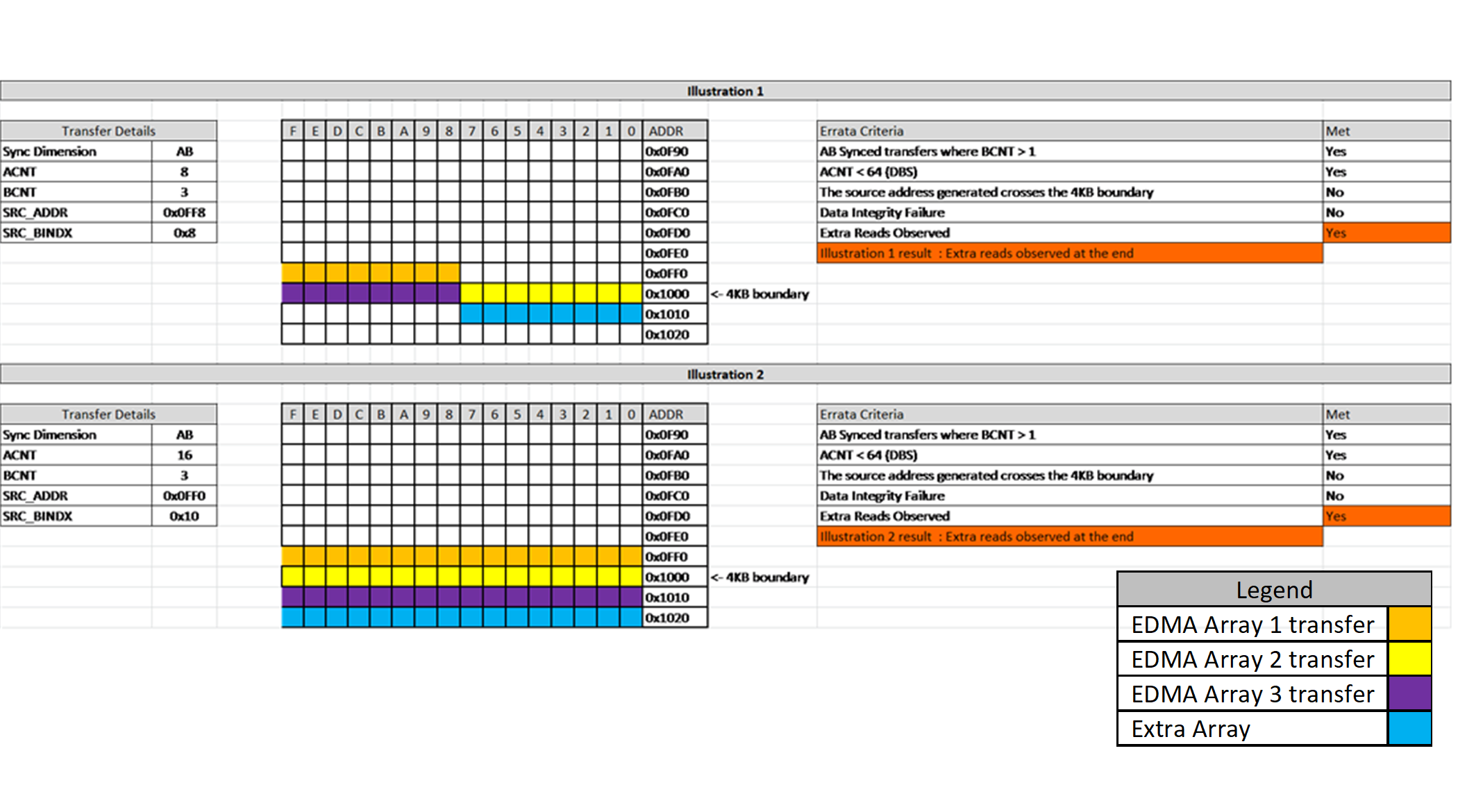
No | No | Yes (see Figure 6-3) |
Source Addressing crossing 4-KB boundary cross
condition [1] in Table 6-1 is defined as follows:
[X(i) = LSB_12bits(SRC_ADDR
+ i * SRC_BIDX)] + ACNT > 0x1000
where 0 <= i
< BCNT
Source Addressing crossing 4-KB boundary cross
condition [2] in Table 6-1 is defined as follows:
LSB_12bits(SRC_ADDR) + (ACNT
* BCNT) > 0x1000
For the and expressions above, note that the SRC_ADDR is candidate source address considering the C-dimension. If CCNT > 1, then, the SRC_ADDR would be every candidate source address for all CCNTs depending on the type of transfer and the SRCCIDX.
For each extra read in Scenario ID #3 for which Condition [1] is applicable, each index i above that satisfies the condition results in extra read from starting address SRC_ADDR + (i + 1) * SRCBIDX and of length equal to the distance from the start address to the boundary [that is, 0x1000 – X(i)]. Note: length < ACNT.
 Figure 6-1 Scenario ID #3 – Extra
Reads
Figure 6-1 Scenario ID #3 – Extra
ReadsFor each extra read Scenario ID #4 in for which Condition [1] is applicable, there is an extra read from starting address SRC + BCNT * ACNT (=SRCBIDX) of length equal to the distance of the start address to the boundary [that is, length is 0x1000 – X(i)], where i is the index of one and only 4-KB boundary crossing condition. Note: length < ACNT.
 Figure 6-2 Scenario ID #4 – Extra
Reads
Figure 6-2 Scenario ID #4 – Extra
ReadsFor the extra read Scenario ID #5 in for which Condition [2] is applicable, there is an extra read from starting address SRC + BCNT * ACNT (=SRCBIDX) of length equal to the distance of the start address and is of length ACNT.
 Figure 6-3 Scenario ID #5 – Extra
Reads
 Figure 6-4 Scenario ID #1 – Data
Integrity Failure
Figure 6-4 Scenario ID #1 – Data
Integrity FailureWorkaround(s):
Workaround #1 - ALL SCENARIO IDs (see Table 6-1)
Prevent one or more of the conditions necessary for the problematic scenarios to happen.
Workaround #2 - Scenario ID #3, Scenario ID #4, and Scenario ID #5 (see Table 6-1)– EXTRA READS
For Scenario ID #3, Scenario ID #4, and Scenario ID #5– EXTRA READS, another workaround besides avoiding the 4-KB boundary cross conditions, is to ensure that buffers involved in this kind of transfer are positioned so that extra reads stay within the physical memory boundaries. If the extra reads go to Reserved space or space blocked by the Memory Protection Unit (MPU), the TPTC generates a bus error interrupt to the processor.