TIDT232 September 2021
8.1 EMI Scans - Single UCC12050, 5 VOUT, 100 mA
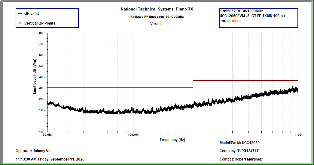
The test results shown in Figure 8-3 and Figure 8-4 demonstrate measured radiated emissions for a single, 5-V, UCC12050 operating at full load where Figure 8-3 shows the result when the receiving antenna is orientated horizontally and Figure 8-4 shows the result when the receiving antenna is orientated vertically.
 Figure 8-3 Horizontal, Ferrite Beads L1, L2, –5.15 dB (920 MHz), 100 % Load (500 mW)
 Figure 8-4 Vertical, Ferrite Beads L1, L2, –5.38 dB (930 MHz), 100 % Load (500 mW)