300 W" />
TIDT262
April 2022
Description
Features
Applications
1
Test Prerequisites
1.1
Voltage and Current Requirements
1.2
Considerations
1.3
Dimensions
2
Testing and Results
2.1
Efficiency Graphs
2.2
Load Regulation
2.3
Line Regulation
2.4
Thermal Images
2.4.1
Further Extensive Thermal Measurements
2.4.1.1
No Forced Cooling
2.4.1.1.1
Thermal Images 4.5 VIN and 20 AOUT
2.4.1.1.1.1
After 1 Minute of Operation
2.4.1.1.1.2
After 2 Minutes of Operation
2.4.1.1.2
Thermal Image 5.5 VIN and 20 AOUT
2.4.1.1.3
Thermal Image 7 VIN and 25 AOUT
2.4.1.1.4
Thermal Image 9 VIN and 30 AOUT
2.4.1.1.5
Thermal Image 12 VIN and 30 AOUT
2.4.1.1.6
Thermal Image 15 VIN and 30 AOUT
2.4.1.1.7
Thermal Image 13.8 VIN and 30 AOUT
2.4.1.2
Forced Cooling
2.4.1.2.1
Thermal Image 4.5 VIN and 20 AOUT
2.4.1.2.2
Thermal Image 5.5 VIN and 20 AOUT
2.4.1.2.3
Thermal Image 7 VIN and 25 AOUT
2.4.1.2.4
Thermal Image 9 VIN and 30 AOUT
2.4.1.2.5
Thermal Image 12 VIN and 30 AOUT
2.4.1.2.6
Thermal Image 15 VIN and 30 AOUT
2.5
Bode Plots
3
Waveforms
3.1
Switching
3.1.1
9-V Input Voltage (Boost Mode)
3.1.1.1
Boost High Side FETs (Q5, Q6)
3.1.1.1.1
Source-Drain (Referenced to VOUT')
3.1.1.1.2
Gate-Source
3.1.1.2
Boost Low Side (Q7, Q8)
3.1.1.2.1
Drain-GND
3.1.1.2.2
Gate-GND
3.1.2
12-V Input Voltage, Transition Mode, Both Legs Switching at ½ FSW
3.1.2.1
Boost High Side FETs (Q5, Q6)
3.1.2.1.1
Source-Drain (Referenced to VOUT')
3.1.2.1.2
Gate-Source
3.1.2.2
Boost Low Side (Q7, Q8)
3.1.2.2.1
Drain-GND
3.1.2.2.2
Gate-GND
3.1.3
16-V Input Voltage, Buck Mode
3.1.3.1
Buck High Side FETs (Q1, Q2)
3.1.3.1.1
Source-Drain (Referenced to VIN')
3.1.3.1.2
Gate-Source
3.1.3.2
Buck Low Side (Q3, Q4)
3.1.3.2.1
Drain-GND
3.1.3.2.2
Gate-GND
3.2
Output Voltage Ripple
3.3
Input Voltage Ripple
3.3.1
Power Stage
3.3.2
Input Terminal, Differential Input Filter Acting
3.4
Load Transients
3.4.1
9-V Input Voltage
3.4.2
12-V Input Voltage
3.4.3
16-V Input Voltage
3.5
Start-Up Sequence
3.5.1
9-V Input Voltage
3.5.2
12-V Input Voltage
3.5.3
16-V Input Voltage
3.6
Shutdown Sequence
3.6.1
9-V Input Voltage
3.6.2
12-V Input Voltage
3.6.3
16-V Input Voltage
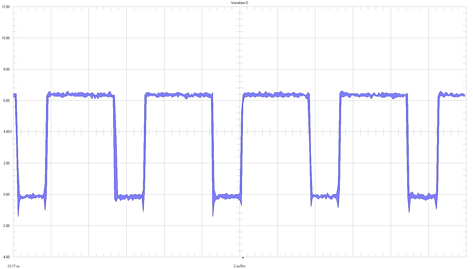
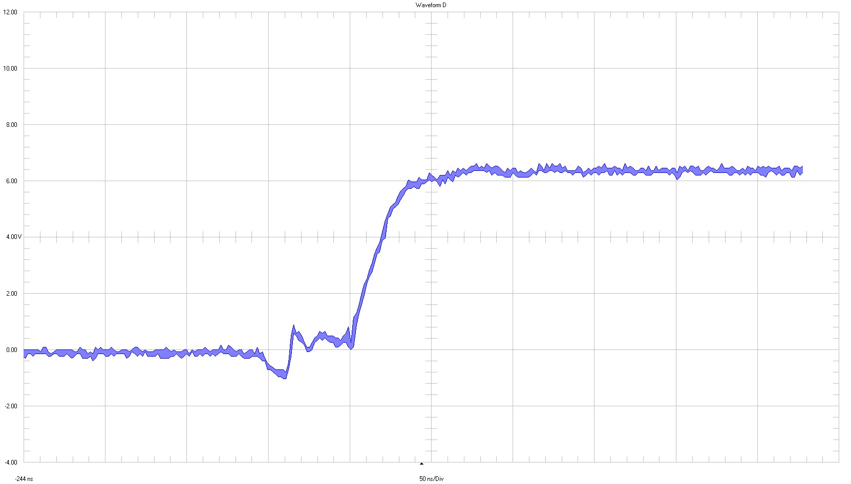
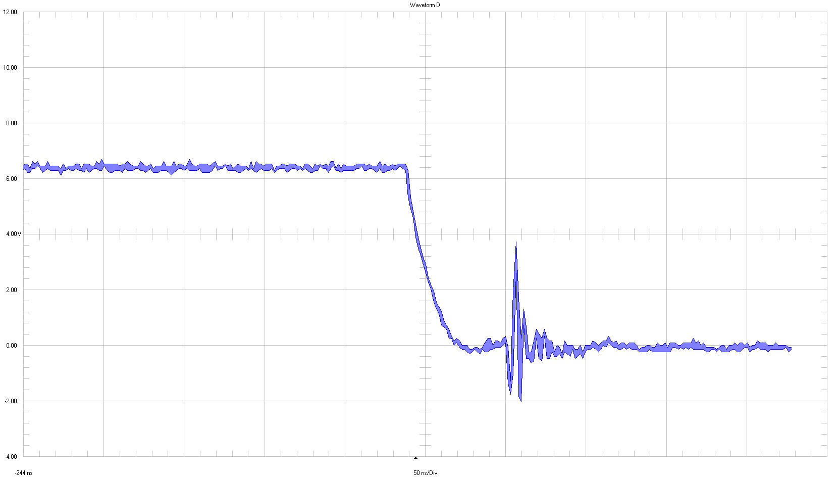
3.1.1.1.2
Gate-Source
CH1 ⇒ 2 V / div
2 µs /div
full bandwidth
CH1 ⇒ 2 V / div
50 ns / div
Figure 3-3
Waveform High-Side FET Gate - Source
千亿体育app官网登录(中国)官方网站IOS/安卓通用版/手机APP
|
米乐app下载官网(中国)|ios|Android/通用版APP最新版
|
米乐|米乐·M6(中国大陆)官方网站
|
千亿体育登陆地址
|
华体会体育(中国)HTH·官方网站
|
千赢qy国际_全站最新版千赢qy国际V6.2.14安卓/IOS下载
|
18新利网v1.2.5|中国官方网站
|
bob电竞真人(中国官网)安卓/ios苹果/电脑版【1.97.95版下载】
|
千亿体育app官方下载(中国)官方网站IOS/安卓/手机APP下载安装
|