TIDT296 September 2022
2.2 Cross Regulation
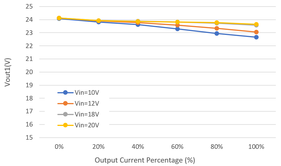
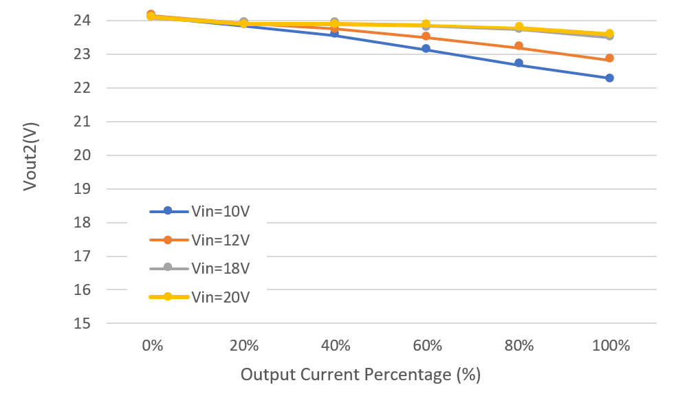
Figure 2-2 and Figure 2-3 illustrate the PMP40994 cross-regulation graphs.
 Figure 2-2 Isolated VOUT1 and
VOUT2 Regulation With Same Percentage Current (Vout1)
 Figure 2-3 Isolated VOUT1 and
VOUT2 Regulation With Same Percentage Current (Vout2)