TIDT318 January   2023


  1.   Description
  2.   Features
  3.   Applications
  4. 1Test Prerequisites
    1. 1.1 Voltage and Current Requirements
    2. 1.2 Required Equipment
    3. 1.3 Considerations
    4. 1.4 Dimensions
    5. 1.5 Test Setup
  5. 2Testing and Results
    1. 2.1 Efficiency Graphs
    2. 2.2 Thermal Images
    3. 2.3 Bode Plots
  6. 3Waveforms
    1. 3.1 Switching
    2. 3.2 Load Transients

Switching

Figure 3-1 shows the main switching waveform.

The waveform in Figure 3-1 is taken at 32 VIN with a maximum load of 30 A per phase. Other conditions include the following: 399-kHz switching, 8-V overshoot, rise time of 6 ns and a fall time of 3 ns.
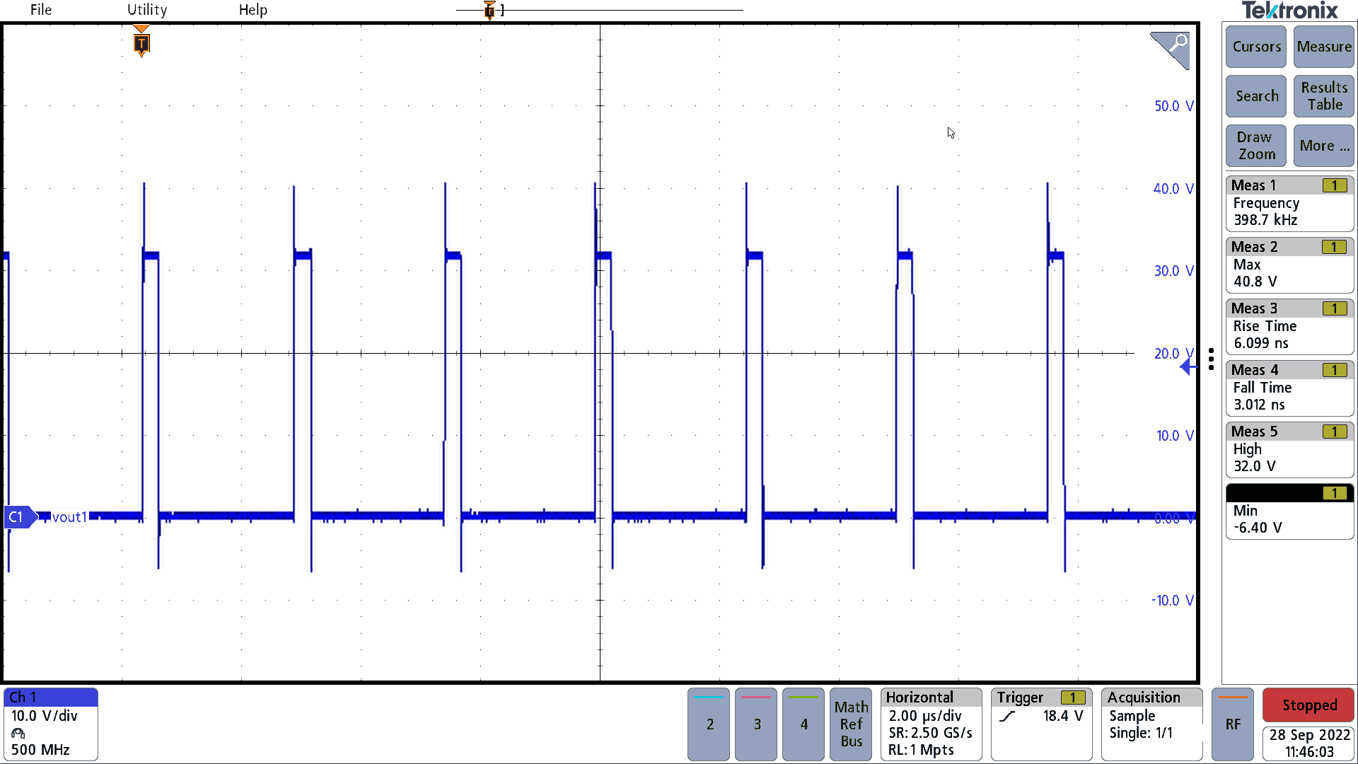
GUID-20221208-SS0I-SK7V-KZNT-RVGFNN38GZ3P-low.png Figure 3-1 Main Switching Waveform