TIDT333 may 2023
3.3 Short-Circuit Protection
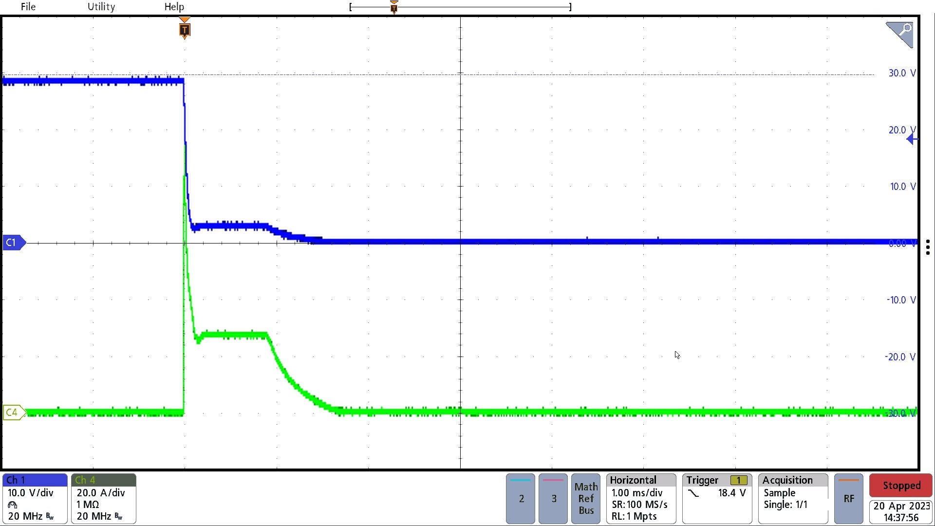
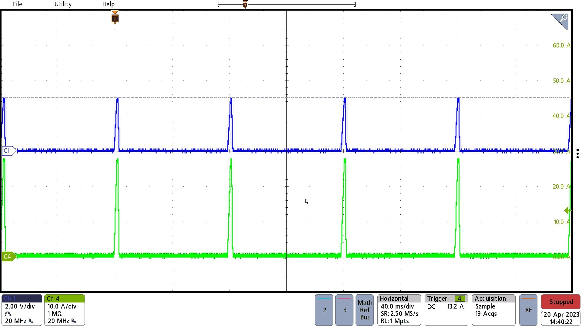
The following figures show the output voltage and current during a short-circuit event. The input voltage was 100 V for both figures. Channel 1 shows the output voltage. Channel 4 shows the output current.
 Figure 3-5 Operation Upon Application of Short
Circuit
 Figure 3-6 Operation During Sustained Short
Circuit