TIDT341 july   2023


  1.   1
  2.   Description
  3.   Features
  4.   Applications
  5. 1Test Prerequisites
    1. 1.1 Voltage and Current Requirements
    2. 1.2 Required Equipment
    3. 1.3 Dimensions
  6. 2Testing and Results
    1. 2.1 Efficiency Graphs
    2. 2.2 Efficiency Data
    3. 2.3 Thermal Images
  7. 3Waveforms
    1. 3.1 Start-Up and Shutdown
    2. 3.2 Charge Enable and Disable
    3. 3.3 Typical Charge Waveforms
    4. 3.4 Typical OTG Waveforms
    5. 3.5 OTG Transient

Typical Charge Waveforms

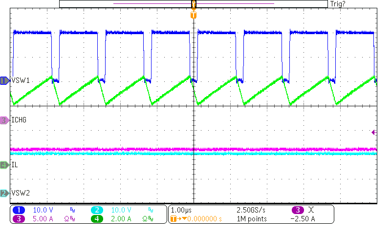
Typical charge waveforms are shown in the following figures.
GUID-20230707-SS0I-KDMK-9MQH-6NXRDRM6KGRP-low.png
VIN = 20 V, VBAT = 16 V, ICHG = 6 A
Figure 3-5 Typical PWM Charge Waveform
GUID-20230718-SS0I-CJKP-CJ0X-RHMLDWZVXKNP-low.png
VIN = 20 V, VBAT = 16 V, ICHG = 1 A
Figure 3-6 Typical PFM Charge Waveform