TIDT353A September 2023 – June 2024
3.1 Load Transient Response
This design follows the M-CRPS standard and has tested 5% to 105%, and 20% to 80% load transient response. The test waveforms are shown in the following figures.
In Figure 3-1 and Figure 3-2, channel 1 in dark blue is Vsw of the primary leg; channel 2 in light blue is the PWM of the primary high side; channel 3 in purple is the output voltage AC portion; channel 4 in green is the primary current.
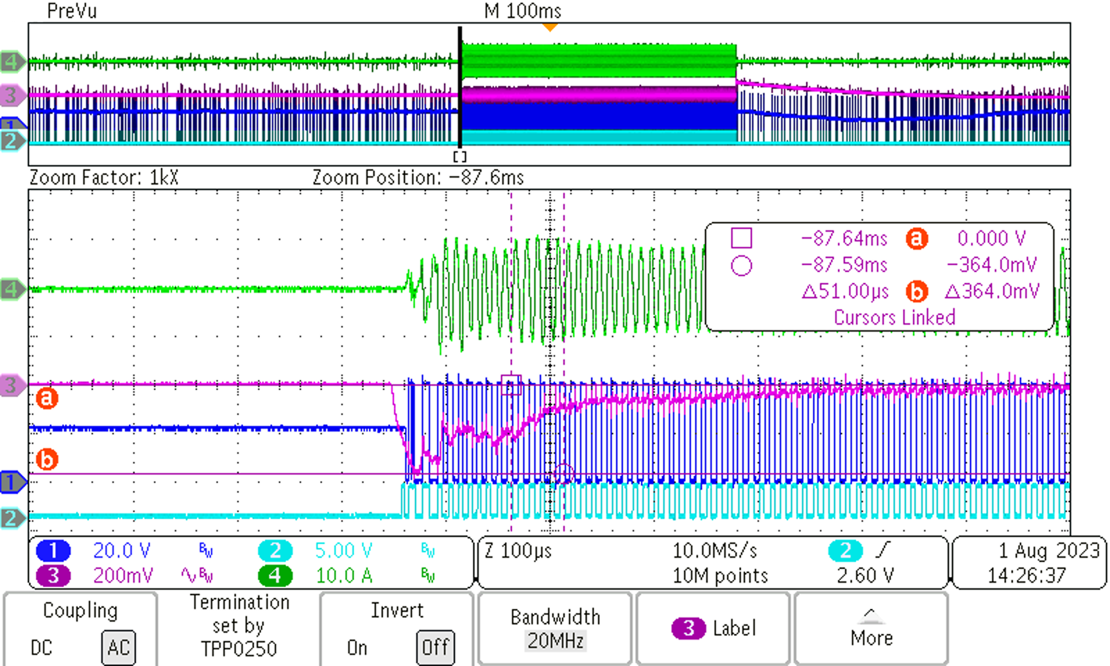 Figure 3-1 Load Transient: 380 VIN,
Load Step: 0 A to 84 A, 2.5 A/μs
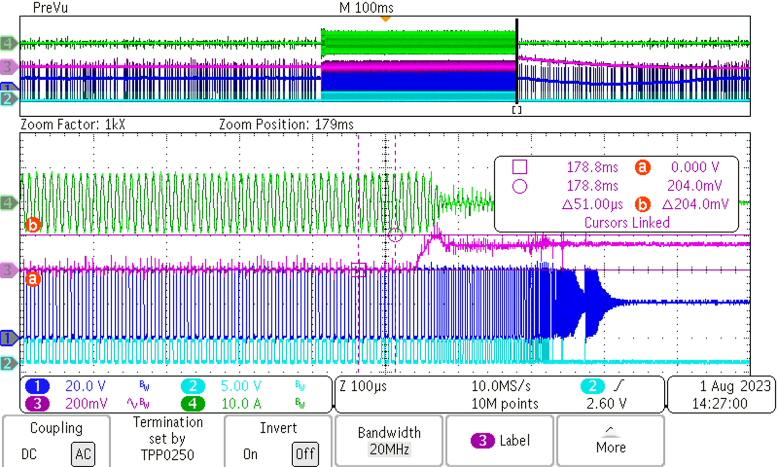 Figure 3-2 Load Transient: 380 VIN,
Load Step: 84 A to 0 A, 2.5 A/μs
In the following waveforms, channel 1 in dark blue is load current; channel 3 in purple is the AC portion of output voltage; channel 4 in green is primary current.
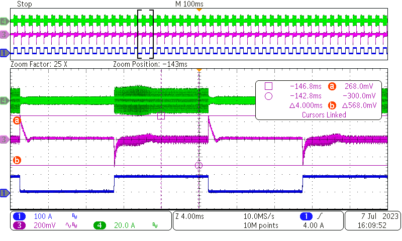 Figure 3-3 Load Transient: 380 VIN, Load
Step:
Figure 3-3 Load Transient: 380 VIN, Load
Step:4 A 10 ms and 88 A 10 ms, 2.5 A/μs
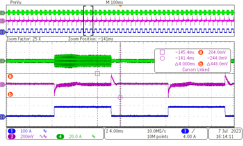 Figure 3-5 Load Transient: 410 VIN, Load
Step:
Figure 3-5 Load Transient: 410 VIN, Load
Step:4 A 10 ms and 88 A 10 ms, 2.5 A/μs
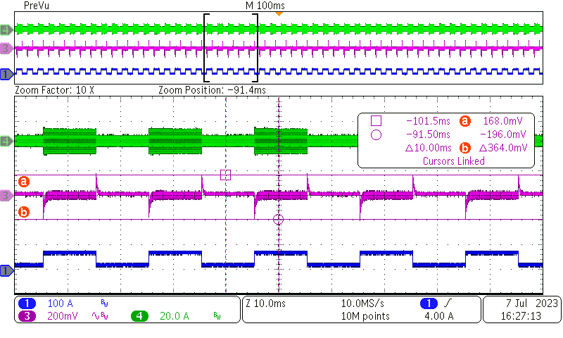 Figure 3-7 Load Transient: 380 VIN, Load
Step:
Figure 3-7 Load Transient: 380 VIN, Load
Step:17 A 10 ms and 67 A 10 ms, 2.5 A/μs
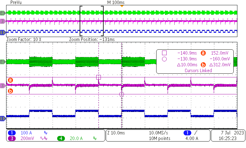 Figure 3-9 Load Transient: 410 VIN, Load
Step:
Figure 3-9 Load Transient: 410 VIN, Load
Step:17 A 10 ms and 67 A 10 ms, 2.5 A/μs
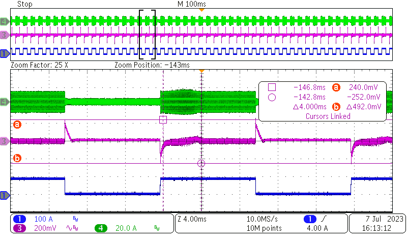 Figure 3-4 Load Transient: 400 VIN, Load
Step:
Figure 3-4 Load Transient: 400 VIN, Load
Step:4 A 10 ms and 88 A 10 ms, 2.5 A/μs
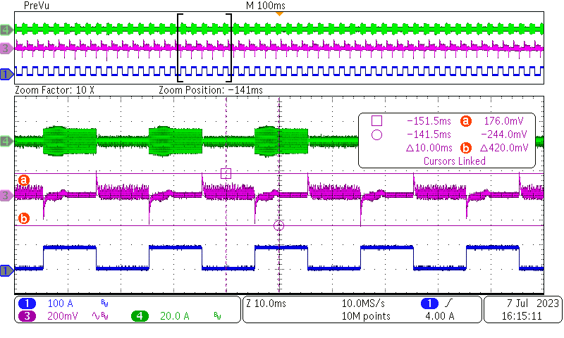 Figure 3-6 Load Transient: 420 VIN, Load
Step:
Figure 3-6 Load Transient: 420 VIN, Load
Step:4 A 10 ms and 88 A 10 ms, 2.5 A/μs
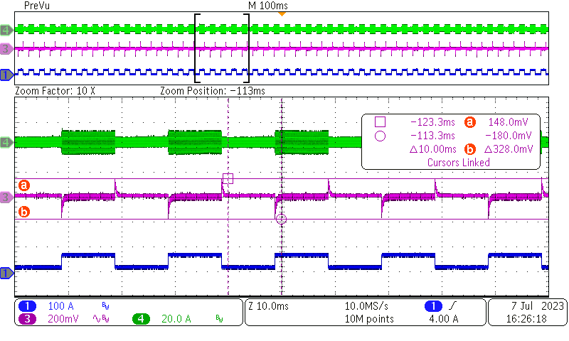 Figure 3-8 Load Transient: 400 VIN, Load
Step:
Figure 3-8 Load Transient: 400 VIN, Load
Step:17 A 10 ms and 67 A 10 ms, 2.5 A/μs
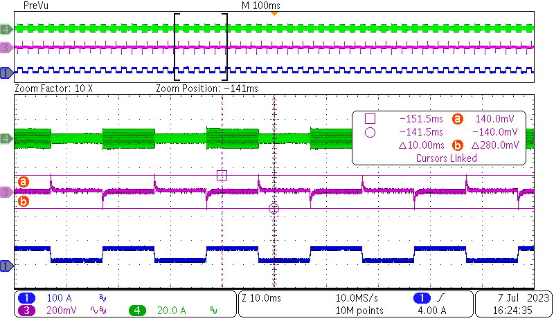 Figure 3-10 Load Transient: 420 VIN, Load
Step:
Figure 3-10 Load Transient: 420 VIN, Load
Step:17 A 10 ms and 67 A 10 ms, 2.5 A/μs