TIDT365 November   2023


  1.   1
  2.   Description
  3.   Features
  4.   Applications
  5. 1Test Prerequisites
    1. 1.1 Voltage and Current Requirements
    2. 1.2 Required Equipment
    3. 1.3 Considerations
    4. 1.4 Dimensions
  6. 2Testing and Results
    1. 2.1 Efficiency Graphs
    2. 2.2 Efficiency Data
    3. 2.3 POUT
    4. 2.4 Idle Power Loss
    5. 2.5 THD
    6. 2.6 Thermal Images
  7. 3Waveforms
    1. 3.1 Switching
    2. 3.2 Dead Time
    3. 3.3 Minimum Pulse on Time of LI
    4. 3.4 Output Waveform

Idle Power Loss

Idle power loss image is shown in the following figure.

The test conditions for the results in Figure 3-22 include a 1-kHz sine-wave frequency, no resistor load, with heat sink, and no airflow.
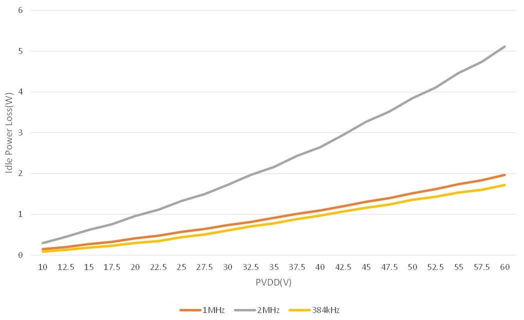
GUID-20231029-SS0I-7VRT-GF4B-MQRLXR7MGZGM-low.jpg Figure 2-8 Idle Power Loss