TIDT365 November 2023
3.3 Minimum Pulse on Time of LI
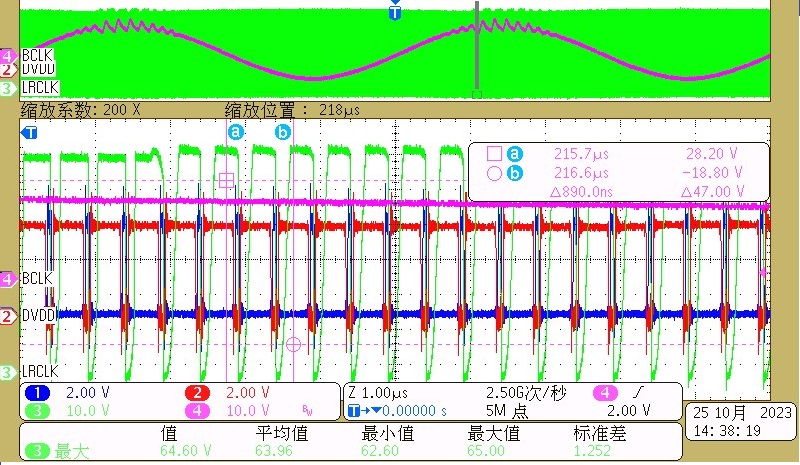
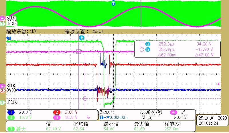
The output voltage waveform at idle load distorts as Figure 3-6 shows when the minimum pulse on time of LI is too small. The limitation for minimum pulse on time is if it is too small, the voltage of the bootstrap capacitor is under UVLO threshold. You can increase the value of C12 to get a smaller minimum on time.
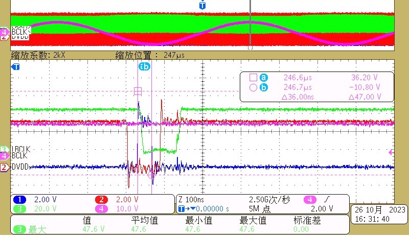
The minimum pulse on time images are shown in the following figures.
 Figure 3-6 Output Voltage (Pink)
Oscillate at Idle Load With too Small Pulse on Time of LI (Blue)
 Figure 3-8 Minimum Pulse on Time of
LI (Blue) With C12 0.1 μF
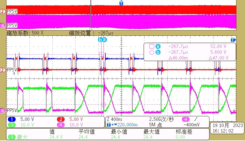
 Figure 3-7 Abnormal Vds of High-Side
GaN (Pink) and Low-Side GaN (Green) at Idle Load With too Small Pulse on
Time of LI (Red)
 Figure 3-9 Minimum Pulse on Time of
LI (Blue) With C12 0.47 μF