TIDT397 October   2024


  1.   1
  2.   Description
  3.   Features
  4.   Applications
  5. 1Test Prerequisites
    1. 1.1 Voltage and Current Requirements
    2. 1.2 Considerations
    3. 1.3 Dimensions
  6. 2Testing and Results
    1. 2.1 Waveforms
      1. 2.1.1 Start-Up
      2. 2.1.2 Steady State Waveforms
      3. 2.1.3 Load Transient
      4. 2.1.4 Output Voltage Ripple
    2. 2.2 Loop Response
    3. 2.3 Efficiency
    4. 2.4 Thermal Images

Steady State Waveforms

Steady state switching waveforms are shown in Figure 2-3 through Figure 2-7.
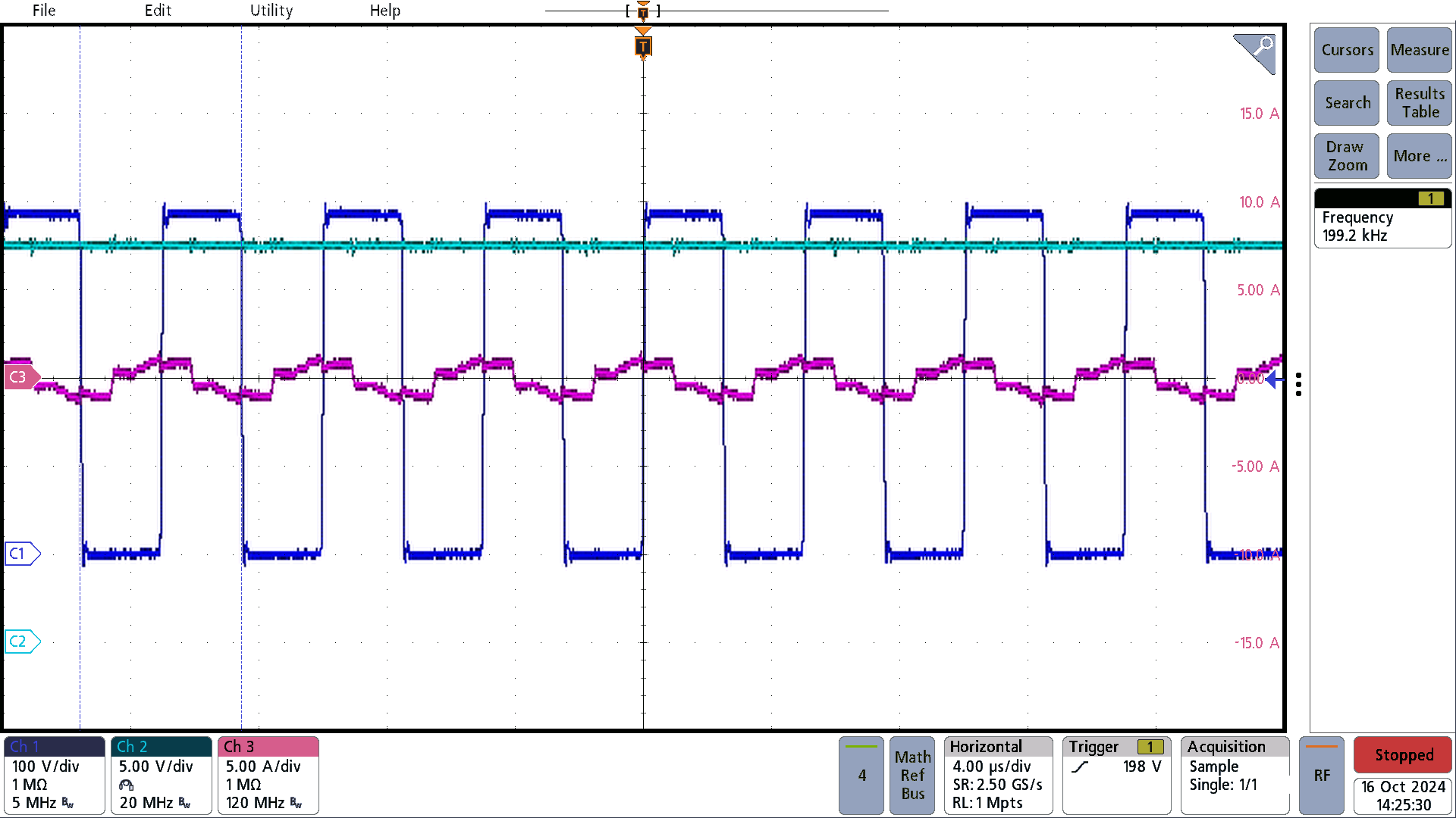
PMP23463 385Vin, No
                    Load
C1 = switch node, C2 = Vout, C3 = resonant current
Figure 2-3 385Vin, No Load
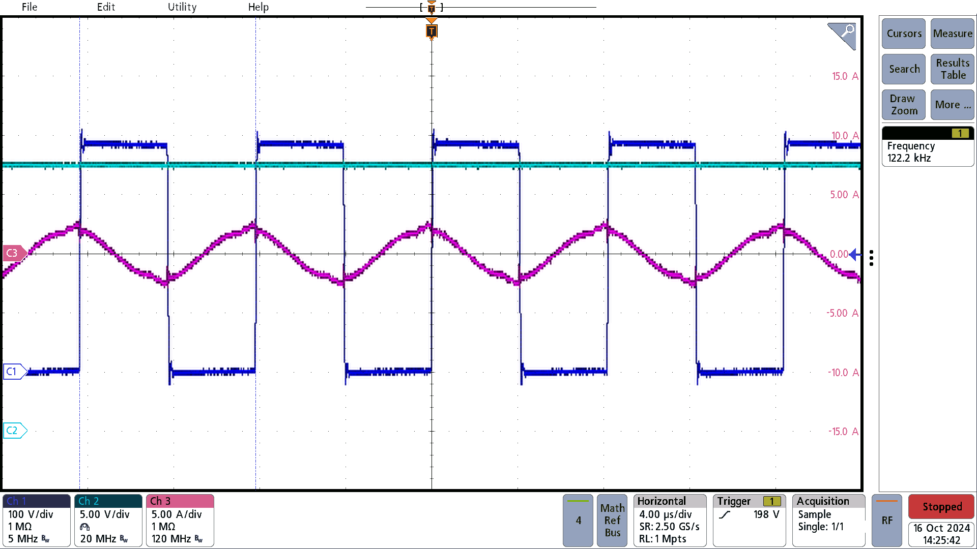
PMP23463 385Vin, 3A
                    Load
C1 =switch node, C2 = Vout, C3 = resonant current
Figure 2-4 385Vin, 3A Load
PMP23463 385Vin, 6A
                    Load
C1 = switch node, C2 = Vout, C3 = resonant current
Figure 2-5 385Vin, 6A Load
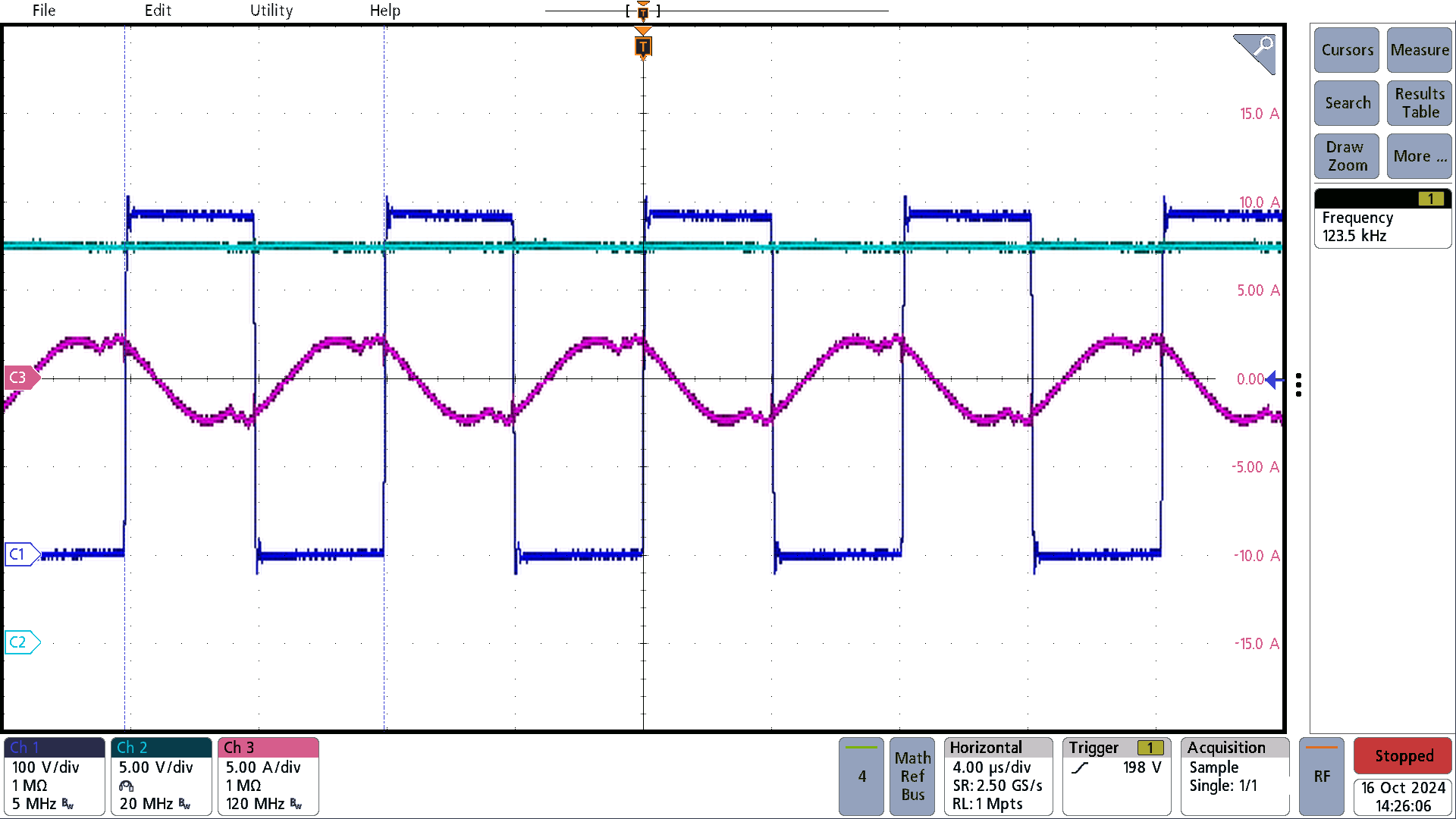
PMP23463 385Vin, 9A
                    Load
C1 =switch node, C2 = Vout, C3 = resonant current
Figure 2-6 385Vin, 9A Load
PMP23463 385Vin, 13.5A
                    Load
C1 = switch node, C2 = Vout, C3 = resonant current
Figure 2-7 385Vin, 13.5A Load