TIDT411 September 2024
3.1 Switching
Switching behavior is shown in Figure 3-1 through Figure 3-10.
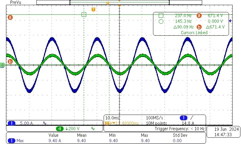 Figure 3-1 PFC, 90Vac Input, Full Load
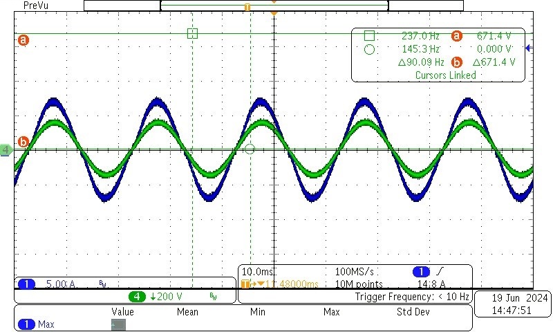 Figure 3-2 PFC, 110Vac Input, Full Load
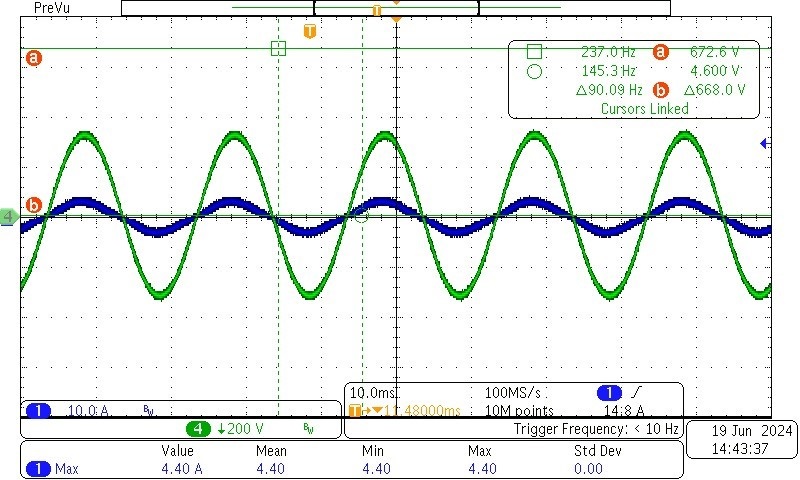 Figure 3-3 PFC, 230Vac Input, Full
Load
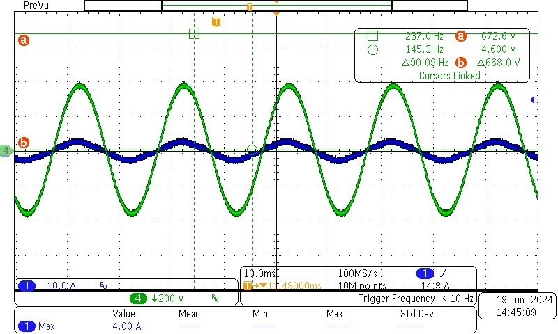 Figure 3-4 PFC, 264Vac Input, Full
Load
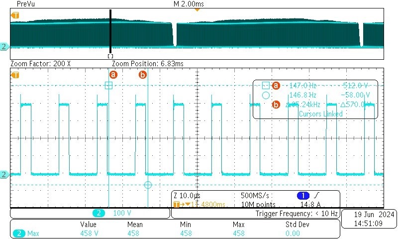 Figure 3-5 PFC, 90Vac Input, Full
Load, Switch Node Waveform
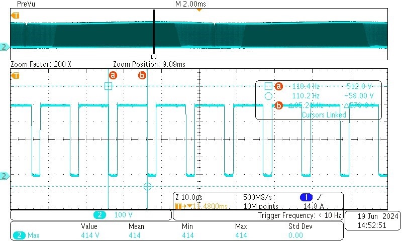 Figure 3-6 PFC, 264Vac Input, Full
Load, Switch Node Waveform
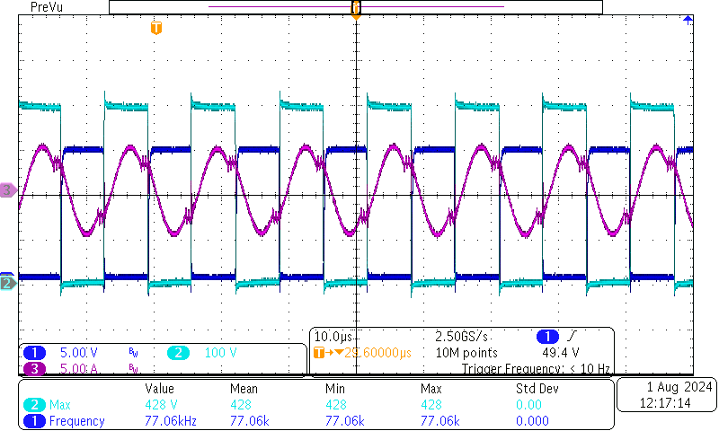 Figure 3-7 LLC, 48V, 10.4A
Load
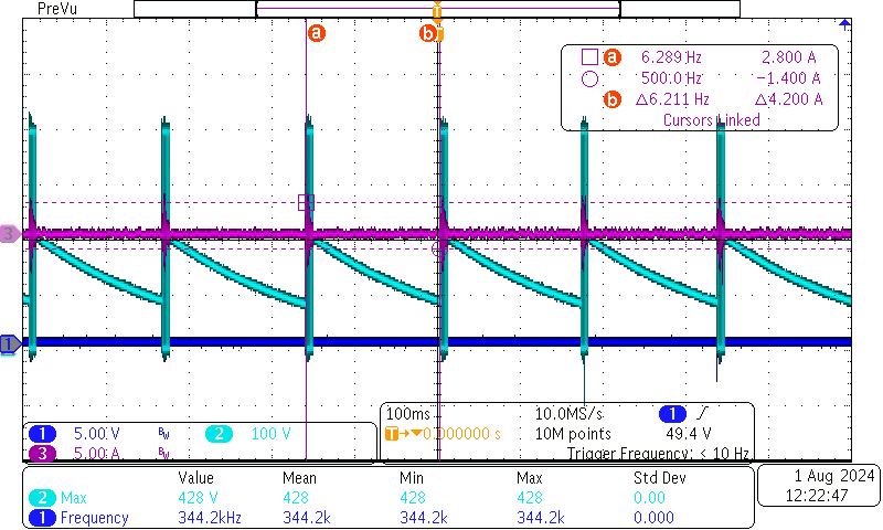 Figure 3-8 LLC, 48V, 0A Load
Note: CH1: Vgs CH2: Vds CH3: Resonant tank
current
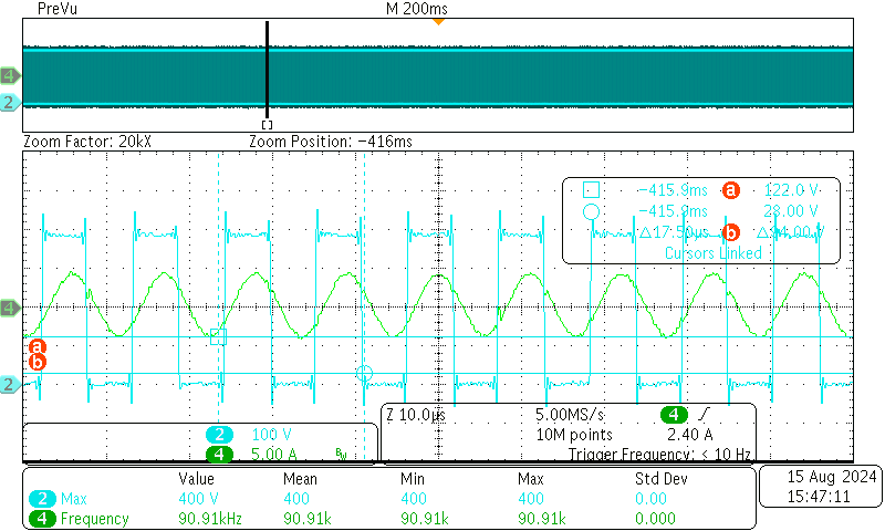 Figure 3-9 LLC, 40V, 10.4A
Load
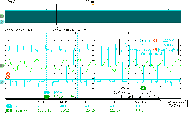 Figure 3-10 LLC, 30V, 10.4A
Load
Figure 3-10 LLC, 30V, 10.4A
LoadNote: CH2: Vds CH4: Resonant tank current