TIDT412A October   2024  – November 2024


  1.   1
  2.   Description
  3.   Features
  4.   Applications
  5. 1Test Prerequisites
    1. 1.1 Voltage and Current Requirements
    2. 1.2 Required Equipment
    3. 1.3 Considerations
    4. 1.4 Dimensions
  6. 2Testing and Results
    1. 2.1 Efficiency Graphs
    2. 2.2 Efficiency Data
    3. 2.3 Thermal Images
    4. 2.4 Bode Plots
    5. 2.5 PWM Duty Cycle Versus Output Voltage
  7. 3Waveforms
    1. 3.1 Switching
    2. 3.2 Output Voltage Transitions
    3. 3.3 Load Transients
    4. 3.4 High Current Load Transients
    5. 3.5 Start-up and Shutdown Sequences
    6. 3.6 Overvoltage Protection
    7. 3.7 Reverse Voltage Protection

Start-up and Shutdown Sequences

Figure 3-10 and Figure 3-11 show the start-up waveforms with an input voltage of 48V, a load of 2.5Ω, and at an output voltage of 6V and 20V respectively.
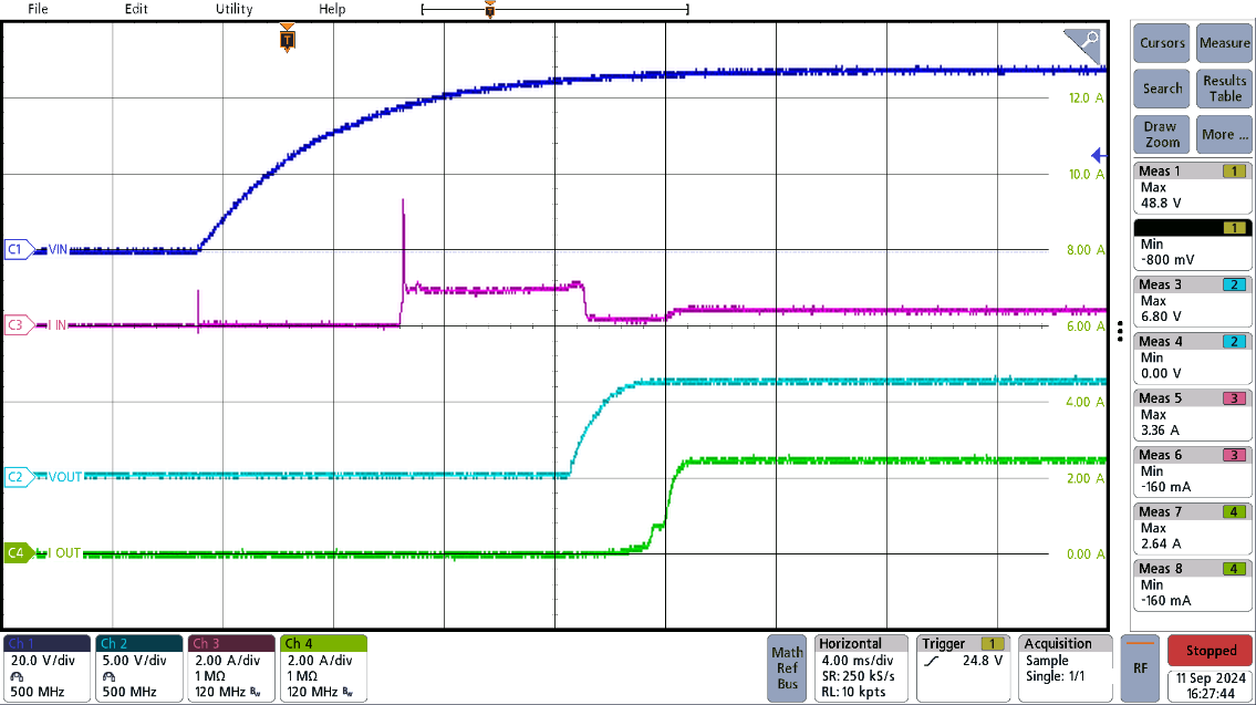
PMP23468 6VOUT Start-Up Figure 3-10 6VOUT Start-Up
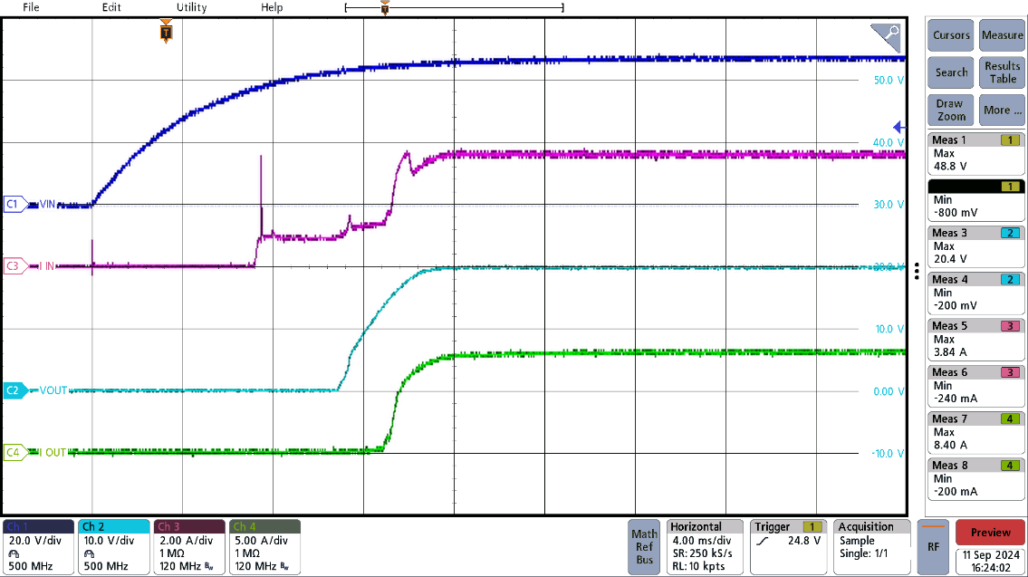
PMP23468 20VOUT Start-Up Figure 3-11 20VOUT Start-Up

Figure 3-12 shows shutdown waveforms with an input voltage of 48V, a load of 2.5Ω, at an output voltage of 6V.
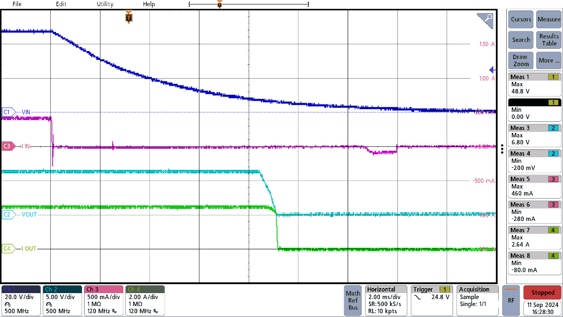
PMP23468 6VOUT Shutdown Figure 3-12 6VOUT Shutdown