TIDUAH1A August 2015 – April 2018
2.4.2.2 DC Analog Output Driver—Current and Voltage
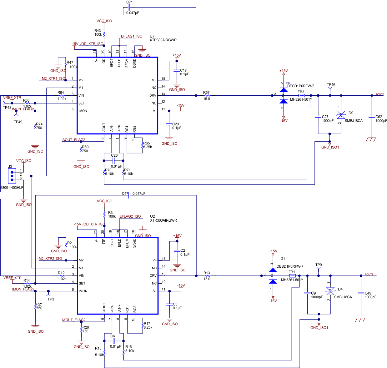
Figure 12 shows the XTR300 device, which is used as an output driver. The XTR300 device is a complete, single-channel output driver for industrial and process control applications. The XTR300 device is capable of sourcing and sinking voltage and current over the standard industrial output ranges that are configured through external gain setting resistors. The output can be configured for IOUT mode or VOUT mode based on a digital control signal.
 Figure 12. XTR300 Interface
The XTR300 device is configured for ±24 mA or ±10 in this design.
The resistor numbers in the below calculations are for circuits associated with the U7 integrated circuit (IC) in the schematic. The same calculations are valid for circuits associated with the U2 IC in the schematic.
The output current or voltage setting depends on the R63 (SET resistor) and the R65 (gain resistor).
Solve for IOUT mode in the following Equation 3:
By rearranging Equation 3 for R63 in Equation 4:
In this design, a 1.02-kΩ 0.1% tolerance is used for R63.
For the VOUT mode, see Equation 5:
Rearrange Equation 5 for R65 in the following Equation 6:
In this design, an 8.25-kΩ 0.1% tolerance is used for R65.
C71 is a compensation capacitor that compensates the control loop for the XTR300 output driver, providing a stable output with output capacitance. The XTR300 datasheet recommends a value of 47 nF, which has been used in this design.
The three open-collector error signals are provided to indicate output related error. These signals include overcurrent or open-load errors (EFLD) that exceed the common-mode input range at the IA inputs (EFCM) and overtemperature warnings (EFOT). Isolated monitoring of the error flags for both XTR300 devices is accomplished in this design by ORing the three open-collector error flags for each XTR300 device and then sending them individually through the digital isolator. Load monitoring is possible in both VOUT mode and IOUT mode using the IMON and IAOUT pins.
See Section 3.1.1.1 to change the analog output to voltage or current mode.