TIDUCJ0G November 2016 – April 2020
6.4.2.2 Designing Current Loop Compensator
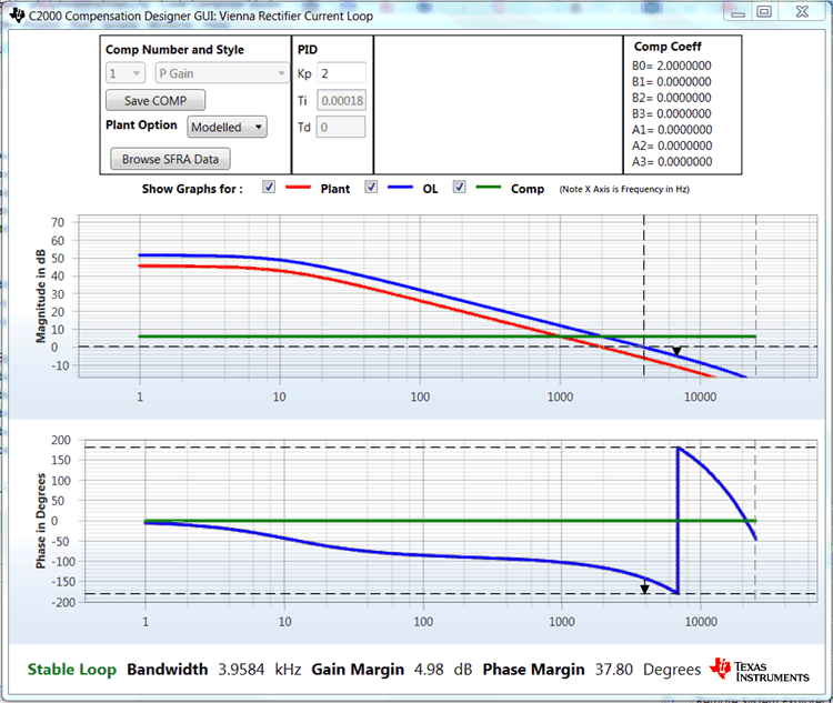
- Compensation Designer will then launch, with the model of the current loop plant with parameters specified on the powerSUITE page. Proportional gain value can then be changed to ensure stable closed loop operation. Stability of the system when using the designed compensator can be verified by observing the gain and phase margins on the open loop transfer function plot in the Compensation Designer, as shown in Figure 28.
- When satisfied with the proportional gain, click Save COMP. This will save the compensator values into the project.
- Note: If the project was not selected from the solution adapter, changes to the compensator will not be allowed to design one's own solution. Select the solution through the solution adapter.
- Close the Compensation Designer, and return to the powerSUITE page.
Note: The P gain in the code is set to 2.0, this gain would give a OL plot with margins that may look too small; however, this gain has been adjusted keeping in mind the actual measurements from the design where the measured gain is slightly lower. Therefore, a higher gain to the compensator can be applied without sacrificing the actual margins.
