TIDUCJ0G November 2016 – April 2020
6.4.5.3 Test procedure
- Follow the step 1~3 in section 6.4.4.1
- Open thevienna_user_settings.h, Change the setting from #define ETHERNET_DEMO ETHERNET_DISABLED to #define ETHERNET_DEMO ETHERNET_ENABLED. Click Save. This enables to send the command signal by GUI page through ethernet. Notes: Do not forget to change this settings back if ethernet is not used and normal INCR_BUILD 4 is selected)
- Follow the step 1~2 in section 6.4.4.2
- Connect CM core and load enet_lwip_cm.out to the CM core. enet_lwip_cm.out is in the folder c2000ware-digital-power-sdk\solutions\tidm_1000\f2838x\enet_lwlp_cm\examples\enet_lwip\cm\ccs\Flash. Notes: It is not suggested to change enet_lwip_cm.out file. However, if customers would like to change it, the project (c2000ware-digital-power-sdk\solutions\tidm_1000\f2838x\enet_lwlp_cm\examples\enet_lwip) needs to be open independently in the CCS and the driverlib (c2000ware-digital-power-sdk\c2000ware\driverlib\f2838x\driverlib_cm) needs to be added to the project to recompile.
- Click Texas Instruments XDS100v2 USB Debug Probe_0/C28xx_CPU1 and click Run
- Click Texas Instruments XDS100v2 USB Debug Probe_0/C28xx_CPU1 and click Halt
- Enable real-time mode by hovering the mouse on the buttons on the horizontal toolbar and clicking the
 button.
 - Click Texas Instruments XDS100v2 USB Debug Probe_0/C28xx_CPU1 and click Run
- Click Texas Instruments XDS100v2 USB Debug Probe_0/Cortex_M4_0 and click Run
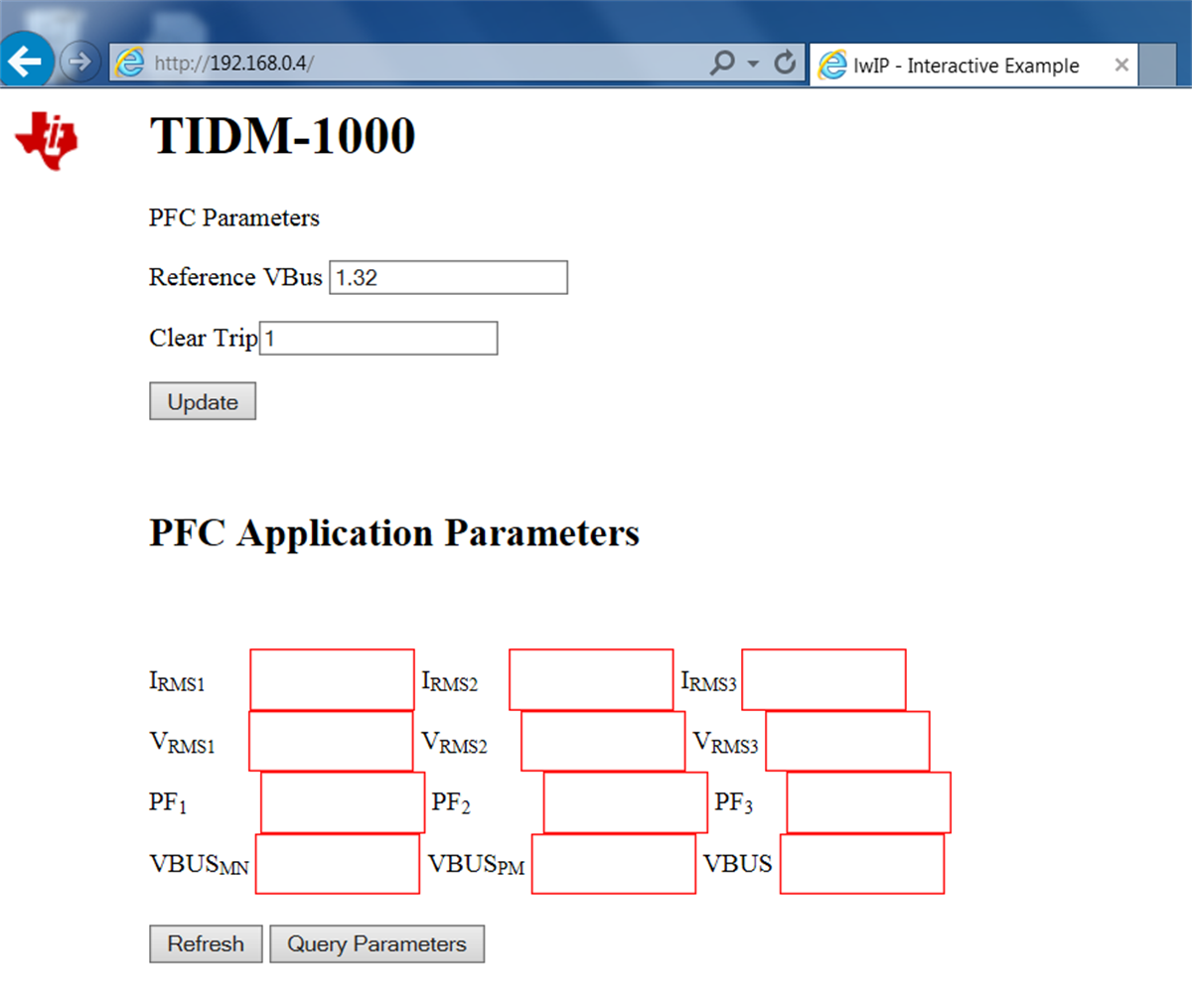
- Open a Web browser (Chrome/IE) on the PC2 to which TMDSCNCD28388D control card is connected and type 192.168.0.4. You should see a GUI page similar to Figure 51
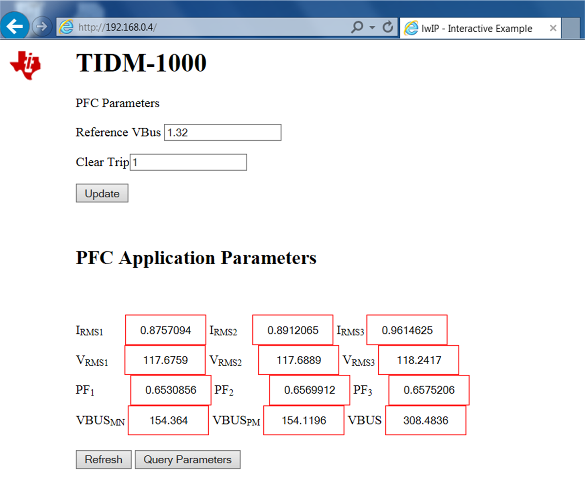
- Gradually increase the input voltage to 120V. Check all the parameters in the expression window. Click the “Query parameters” and then click Refresh to display the parameters in the web page. All the parameters should appear in the GUI page Figure 52. Compare those values with the values shown in the expression window. Make sure all the displayed parameters in GUI are correct. Do not go forward if this step is not fully verified.
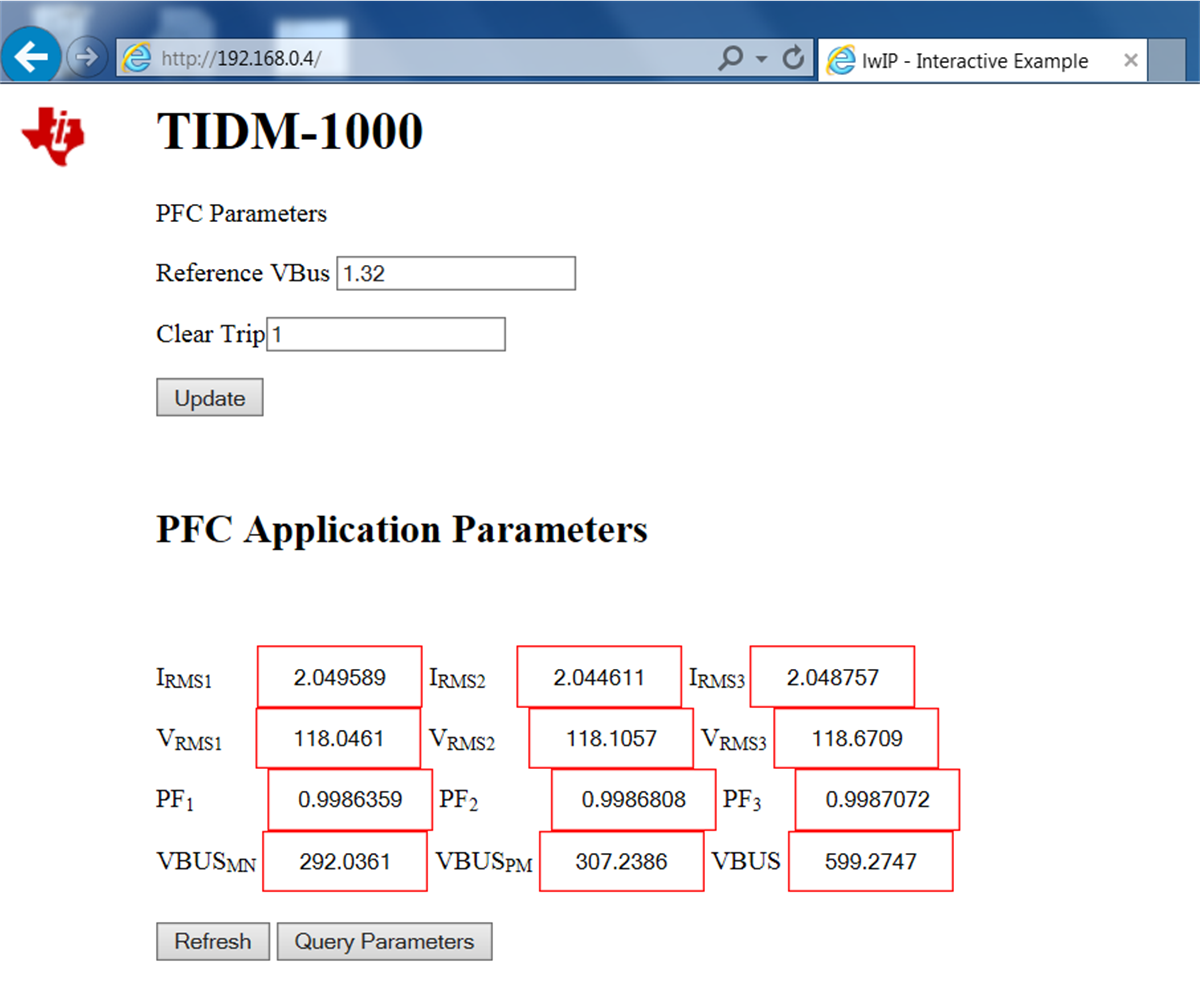
- Now, make sure the Reference Vbus is 1.32 which is the per unit value and the Clear Trip is 1. Click the Update button and it should start PFC. Click the Query parameters and then click Refresh to display the parameters in the webpage. If everything is correct, all the parameters should be updated as Figure 53.
- The final step is to change the "Reference Vbus" to 1 and click Update. The output voltage should decrease to around 450V. Other "Reference Vbus" less than 1.32 can be chosen.
Figure 51. Ethernet GUI Page of TIDM-1000 

Figure 52. Ethernet GUI Page Before Starting PFC 

Figure 53. Ethernet GUI Page After Starting PFC 
