TIDUCL3 February 2017
- 1 Overview
- 2 Resources
- 3 Features
- 4 Applications
- 5 Design Images
- 6 System Overview
-
7 System Design Theory
- 7.1 PCB and Form Factor
- 7.2 Optimizing Board Performance Based on LED String Voltage and Current
- 7.3 Switching Frequency
- 7.4 Output Overvoltage Protection (OVP)
- 7.5 Current Monitoring (IMON)
- 7.6 Thermal Foldback
- 7.7 Clock Generation (PWM)
- 7.8 Onboard Supply and Setting Duty Cycle
- 7.9 Buffering, Averaging, and Filtering
- 7.10 Boost Converter
- 8 Getting Started Hardware
- 9 Testing and Results
- 10Design Files
- 11Related Documentation
- 12About the Author
6.4.4 TL431-Q1
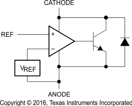
The TL431-Q1 is a three-terminal adjustable shunt regulator with specified thermal stability over applicable automotive temperature ranges (see Figure 5). The output voltage can be set to any value between VREF (approximately 2.5 V) and 36 V, with two external resistors. This device has a typical output impedance of 0.2 Ω. Active output circuitry provides a sharp turnon characteristic, making this device an excellent replacement for Zener diodes in many applications, such as onboard regulation, adjustable power supplies, and switching power supplies.
 Figure 5. TL431-Q1 Functional Block Diagram