TIDUES6 August   2020  – MONTH 


  1.   Description
  2.   Resources
  3.   Features
  4.   Applications
  5.   5
  6. 1System Description
    1. 1.1 Key System Specifications
  7. 2System Overview
    1. 2.1 Block Diagram
    2. 2.2 Design Considerations
    3. 2.3 Highlighted Products
      1. 2.3.1 DRV8906-Q1
      2. 2.3.2 DRV8873-Q1
      3. 2.3.3 TPS1HB16-Q1
      4. 2.3.4 LM2904B-Q1
      5. 2.3.5 TLIN1028-Q1
    4. 2.4 System Design Theory
      1. 2.4.1 Mirror XY and LED Driver
      2. 2.4.2 Mirror Fold Driver
      3. 2.4.3 Mirror Heater Driver for Defogging and De-icing
      4. 2.4.4 Electrochromic Mirror Driver
        1. 2.4.4.1 Sallen-Key Low-Pass Filter
        2. 2.4.4.2 High-Current Buffer Amplifier
        3. 2.4.4.3 Buffer Amplifier Stability for Very-Large Capacitive Loads
        4. 2.4.4.4 Fast Discharge of Large Capacitive Load
      5. 2.4.5 SBC - LIN Communication Interface and System Supply
  8. 3Hardware, Software, Testing Requirements, and Test Results
    1. 3.1 Required Hardware and Software
      1. 3.1.1 Hardware
    2. 3.2 Testing and Results
      1. 3.2.1 Test Setup
      2. 3.2.2 Test Results
        1. 3.2.2.1 Reverse Battery Protection
        2. 3.2.2.2 X&Y Motors and LED Driver
        3. 3.2.2.3 Thermal Performance
  9. 4Design Files
    1. 4.1 Schematics
    2. 4.2 Bill of Materials
    3. 4.3 Altium Project
    4. 4.4 Gerber Files
    5. 4.5 Assembly Drawings
  10. 5Software Files
  11. 6Related Documentation
    1. 6.1 Trademarks
    2. 6.2 Third-Party Products Disclaimer
  12. 7Terminology

Electrochromic Mirror Driver

The electrochromic (EC) mirror utilizes a proprietary electrochromic chemical placed between two conductive layers and glass panels. When a voltage is applied to these conductive elements, the current flow through the chemical causes it to change in color and darken. Electrically, the electrochromic mirror behaves like a very large capacitor, typically greater than 1 F, as well as a small shunt resistance. The total capacitance measured largely depends on the total area of the mirror.

Figure 2-10 shows the EC mirror driver schematic.
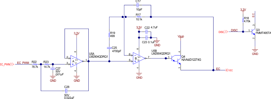
GUID-D571E454-F245-465B-AFFE-304F2E93ACF2-low.gifFigure 2-10 Electrochromic Mirror Driver Circuit