TIDUF87 November 2024
- 1
- Description
- Resources
- Features
- Applications
- 6
- 1System Description
- 2System Overview
-
3Hardware, Software, Testing Requirements, and Test Results
- 3.1 Hardware Requirements
- 3.2 Software Requirements
- 3.3 Test Setup
- 3.4
Test Procedure
- 3.4.1 Lab Variables Definitions
- 3.4.2 Lab 1. Open-Loop Current Control Single Phase
- 3.4.3 Lab 2. Closed Loop Current Control Single Phase
- 3.4.4 Lab 3. Open Loop Voltage Control Single Channel
- 3.4.5 Lab 4. Closed Loop Current and Voltage Control Single Channel
- 3.4.6 Lab 5. Closed Loop Current and Voltage Control Four Channels
- 3.4.7 Calibration
- 3.5 Test Results
- 4Design and Documentation Support
- 5About the Author
3.2.1 Opening the Project Inside Code Composer Studio
Use the following steps to start a project in Code Composer Studio (CCS):
- Install Code Composer Studio from the Code Composer Studio (CCS) integrated development environment (IDE) tools folder. Version 12.4 or above is recommended.
- Install C2000WARE-DIGITALPOWER-SDK in one of two ways:
- Go to CCS and click on View → Resource Explorer. Under the TI Resource Explorer, go to C2000WARE-DIGITAL-POWER-SDK, and click on the install button.
- Through the C2000Ware Digital Power SDK tools folder
- Once installation completes, close CCS, and open a new workspace. CCS automatically detects powerSUITE. Sometimes CCS must be restarted for the change to take effect.
Note: By default, powerSUITE is
installed with the installation of SDK.
The firmware project can now be imported using one of the following methods:
- Using Resource Explorer
- In the Resource Explorer, under C2000WARE-DIGITAL-POWER-SDK, click on powerSUITE → Solution Adapter Tool.
- Select TIDA-010090 from the list of designs presented under DC-DC section.
- The development kit page is displayed. The icon to run the project appears in the top bar. Click Run Project.
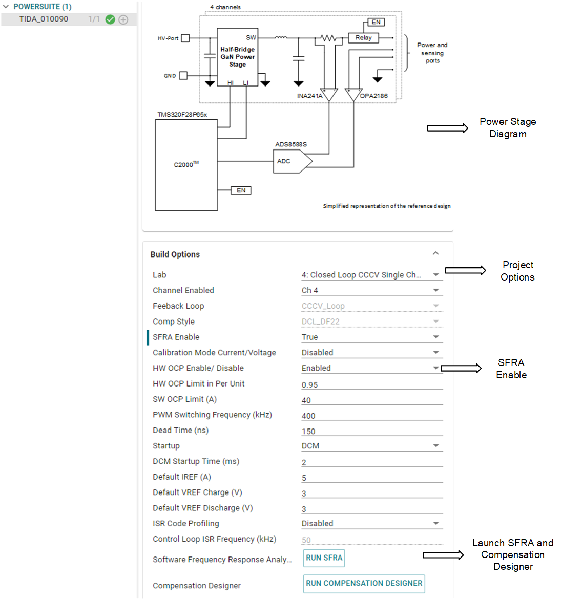
- This action imports the project into the workspace environment, and a configuration page with a GUI similar to Figure 3-2 appears.
- If this GUI page does not appear, see the FAQ section under powerSUITE in the C2000WAREDIGITAL-POWER-SDK resource explorer.
- Direct import from the solution
folder
- The user can also directly import the project by going inside CCS to click Project → Import CCS Projects and browsing to the solution folder located at /solutions/tida_010090/f28p65x/ccs.
- Two project specifications appear: one of the projects is with powerSUITE, and the other without powerSUITE. Clicking on either creates a self-contained folder of the project with all the dependencies inside.
- The non-powerSUITE project is provided for customers who find the powerSUITE GUI limiting or want to remove powerSUITE for production code.
- This document guides the
user through the powerSUITE project, but all the steps can be repeated
with the non-powerSUITE project with modification to the relevant
#definesin the powerSUITEsettings.hfile, which are documented in this design guide.
 Figure 3-2 powerSUITE Page for
the Design