TIDUF87 November 2024
- 1
- Description
- Resources
- Features
- Applications
- 6
- 1System Description
- 2System Overview
-
3Hardware, Software, Testing Requirements, and Test Results
- 3.1 Hardware Requirements
- 3.2 Software Requirements
- 3.3 Test Setup
- 3.4
Test Procedure
- 3.4.1 Lab Variables Definitions
- 3.4.2 Lab 1. Open-Loop Current Control Single Phase
- 3.4.3 Lab 2. Closed Loop Current Control Single Phase
- 3.4.4 Lab 3. Open Loop Voltage Control Single Channel
- 3.4.5 Lab 4. Closed Loop Current and Voltage Control Single Channel
- 3.4.6 Lab 5. Closed Loop Current and Voltage Control Four Channels
- 3.4.7 Calibration
- 3.5 Test Results
- 4Design and Documentation Support
- 5About the Author
3.4.7 Calibration
- To run this lab, make sure the hardware is set up as shown in Figure 3-11. The 2-points calibration method is used to calibrate gain and offset errors.
- To measure current, use an external precision resistor and a DMM, or you can use E-Load current readings. Alternatively, voltage across sense resistors on the TIDA-010090 boards can be used to measure the output current. To measure voltage, use a DMM across the buck converter output voltage and remote sense connections.
- Open the SYSCONFIG page, select
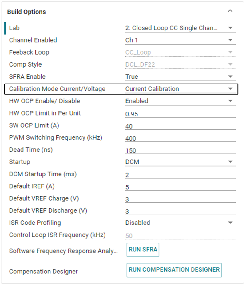
Lab 5, and set Calibration Mode to Current Calibration. Figure 3-32 shows the SYSCONFIG page setting for current calibration.
- Save the SYSCONFIG page, and run the code.
- Open the Expression Window.
- The output current is updated using BT4PH_userParam_V_I_chX->ibatCal_pu parameter.
- Set the BT4CH_userParam_chX->Relay_ON to 1 to enable the output relay.
- Set the BT4CH_userParam_chX->en_bool = 1.
- Set the BT4CH_userParam_chX->ibatCal_pu to "0.05" and "0.3", and note the output current readings.
- Update the actual output current readings in bt4ch_gan_cal.h file.
#define BT4CH_IBAT_ACTUAL_CH1_P1_A ((float32_t)2.5) #define BT4CH_IBAT_ACTUAL_CH1_P2_A ((float32_t)15.00)- Repeat the steps for channel 2, 3 and 4.
-
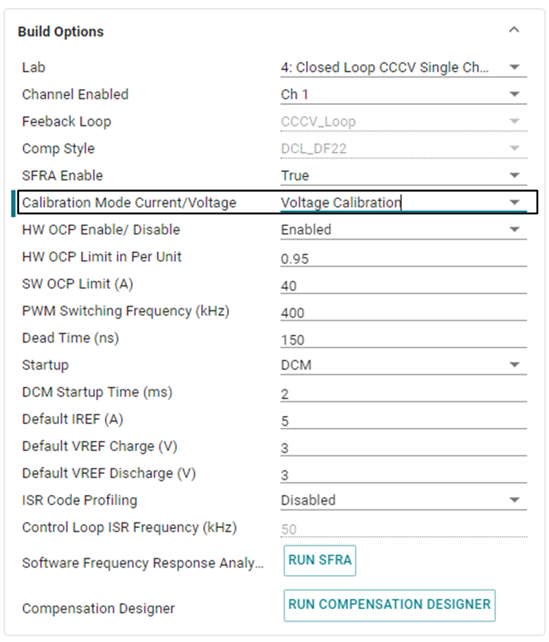
Open the SYSCONFIG page, select Lab 5, and set Calibration Mode to Voltage Calibration. Figure 3-33 shows the SYSCONFIG page setting for voltage calibration.
- Save the SYSCONFIG page, and run the code.
- Open the Expression Window.
- The output current is updated using BT4PH_userParam_V_I_chX->vbatCal_pu parameter.
- Set the BT4CH_userParam_chX->Relay_ON to 1 to enable the output relay.
- Set the BT4CH_userParam_chX->en_bool = 1.
- Set the
BT4CH_userParam_chX->vbatCal_pu to "0.2" and "0.6", and note the
output current readings. Update the actual output current readings in
bt4ch_cal.h
file.
#define BT4CH_VBAT_ACTUAL_CH1_P1_V ((float32_t)1.195) #define BT4CH_VBAT_ACTUAL_CH1_P2_V ((float32_t)3.589) - Repeat the steps for channel 2, 3 and 4.
- Open the SYSCONFIG page, disable the calibration mode.
- When using non-powerSuite version
of the project, Build Settings are directly modified in
solution_settings.hfile. Set CALIBRATION_MODE to (1) for current calibration, and (2) for voltage calibration.#define LAB_NUMBER (5) #define CHANNEL_NUMBER (5) #define CALIBRATION_ENABLED (true) #define CALIBRATION_MODE (1)
 Figure 3-32 Build Options for Current
Calibration
 Figure 3-33 Build Options for Voltage
Calibration