ZHCADT8A December 2023 – June 2024 TAA5212 , TAC5111 , TAC5112 , TAC5211 , TAC5212 , TAD5112 , TAD5212
3.3.4 带有录制功能的自定义模式(主 FS - 较低速率)
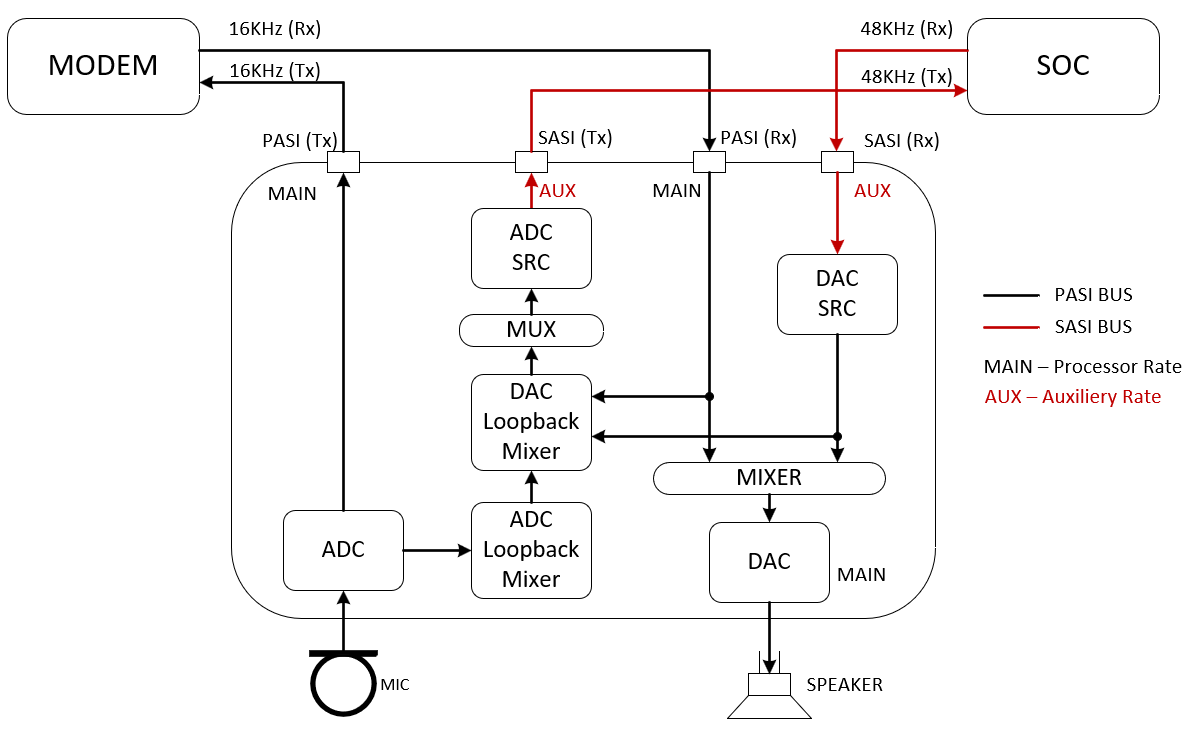
图 3-13 显示了该用例的方框图。PASI 以 16KHz 运行,SASI 以 48KHz 运行。在该用例中,模拟输入 (MIC) 以主 Fs(较低速率)进行采样,并发送至 PASI TX。同一 MIC 输入可与来自 PASI RX 和/或 SASI RX 的 DAC 输入进行混频,并可与 SASI TX 的 SRC 进行上采样。在 DAC 侧,SASI RX 数据可以在 DAC 输出(扬声器)之前与 PASI RX 数据进行混频。
 图 3-13 具有录制功能的自定义模式图
下文显示了 PASI 和 SASI 的 Audio Precision APx555 配置。在该测试用例中,混频器系数保持为默认值(满量程),输入电平会被调整为不超过允许的最大电平(例如 -9dBrG),而不是 0dBrG。
|
PASI APx555: 发生器: 模拟输出 (MIC):1KHz 正弦波,-9dBrG (0dBrG = 2Vrms) 分析器: 输入 1:PASI Tx 的数字音频,其中 Fs = 16KHz、32 位深度 输入 2:DAC 输出(扬声器)的模拟输入 SASI APx555: 发生器: 数字输出:750Hz 正弦波,-9dBFS 分析器: 输入 1:SASI Tx 的数字音频,其中 Fs = 48KHz、TDM、32 位深度 |
##### PASI lower rate than SASI ADC and DAC SRC Testing with Recording ######
# Target Mode, TDM, 32-bit
# Primary and Secondary ASI, multiple of 48KHz Sampling
# GPIO2=Secondary FSYNC, GPIO1=Secondary BCLK, GPI1=Secondary DIN, GPO1=Secondary DOUT for 4x4
#
w a0 00 00            # Set page 0
w a0 01 01            # Software Reset
w a0 02 09            # Wake up with AVDD > 2v and all VDDIO level
w a0 0a 10            # GPIO1 as input
w a0 0b 10            # GPIO2 as input
w a0 0d 02            # GPI1 as input
w a0 0c 71            # GPO1 as Secondary DOUT
w a0 11 a2            # Enable PASI DIN and Set GPI2A as Secondary FSYNC and GPIO1 as Secondary BCLK
w a0 12 60            # Set GPI1A as Secondary DIN
w a0 18 00            # Enable both Primary and Secondary ASI as independent
w a0 34 40            # PASI BCLK is the input clock source
w a0 19 00            # 1 data input and 1 data output for PASI and SASI
w a0 1a 30            # PASI TDM, 32 bit format
w a0 1e 20            # PASI DOUT Ch1 on TDM slot 0
w a0 1f 21            # PASI DOUT Ch2 on TDM slot 1
w a0 28 20            # PASI DIN Ch1 on TDM slot 0
w a0 29 21            # PASI DIN Ch2 on TDM slot 1
w a0 00 03            # Set page 3
w a0 1a 30            # SASI TDM, 32 bit format
w a0 1e 00            # Tri-state SASI DOUT Ch1 on TDM slot 0
w a0 1f 01            # Tri-state SASI DOUT Ch2 on TDM slot 1
w a0 22 20            # SASI DOUT Ch5 on TDM slot 0
w a0 23 21            # SASI DOUT Ch5 on TDM slot 1
w a0 28 20            # SASI DIN Ch1 on TDM slot 0
w a0 29 21            # SASI DIN Ch2 on TDM slot 1
w a0 00 01            # Set page 1
w a0 17 40            # SR-Converter without auto detect
w a0 18 40            # Use PASI Fs as Main Fs
w a0 2c d0            # Enable DAC, Side Chain and Loopback Mixer
w a0 00 11            # Set page 0x11
w a0 0c 00 00 40 00   # Route Main Ch1 to LDAC2 Mixer, full scale
w a0 14 40 00 00 00   # Route Main Ch2 to RDAC2 Mixer, full scale
w a0 4c 00 00 40 00   # Route AUX Ch1 to LDAC2 Mixer, full scale
w a0 54 40 00 00 00   # Route AUX Ch2 to RDAC2 Mixer, full scale
w a0 5e 40 00         # ADC Loopback Ch1 to SC_LDAC2 Mixer to mix with LDAC2, full scale
w a0 64 40 00         # ADC Loopback Ch2 to SC_RDAC2 Mixer to mix with RDAC2, full scale
w a0 00 00            # Set page 0
w a0 50 00            # ADC Ch1 diff input, 5KOhm, 2Vrms ac-coupled, audio band
w a0 55 00            # ADC Ch2 diff input, 5KOhm, 2Vrms ac-coupled, audio band
w a0 64 20            # Configure OUT1P/M as differential from DAC1
w a0 65 20            # Configure OUT1P LINEOUT 0dB audio band
w a0 66 20            # Configure OUT1M LINEOUT 0dB 2Vrms Differential
w a0 6b 20            # Configure OUT2P/M as differential from DAC2
w a0 6c 20            # Configure OUT2P LINEOUT 0dB audio band
w a0 6d 20            # Configure OUT2M LINEOUT 0dB 2Vrms Differential
w a0 76 cc            # Enable Input and Output Ch1 and Ch2
w a0 78 e0            # Power up ADC, DAC and MICBIAS
测试结果
以下各图显示了 SRC 之后 SASI 处的 ADC 输出结果。如此处所示,频率响应 (FFT) 会扫描 20KHz(上采样至 48KHz)。
图 3-14 显示了 SASI TX 输出是 MIC 输入与 SRC 之后 SASI RX 的混合信号。
 图 3-14 SASI ADC 输出
在扬声器输出端,捕获的音调是 SRC 之后 750Hz 的 SASI RX 音调。PASI RX 音调将被静音,PASI TX 为 1KHz 的 MIC 输入。
图 3-15 显示了以 16KHz 频率对来自 MIC 输入的 PASI TX 1KHz 音调进行采样。
图 3-16 显示了该 750Hz 音调是 SRC 之后的 SASI RX 音调,其中 PASI 音调被关闭或静音。
 图 3-15 PASI ADC 输出
 图 3-16 扬声器输出