ZHCS826C January 2012 – November 2023 TPS40170-Q1
PRODUCTION DATA
- 1
- 1 特性
- 2 应用
- 3 说明
- 4 Pin Configuration and Functions
- 5 Specifications
-
6 Detailed Description
- 6.1 Overview
- 6.2 Functional Block Diagram
- 6.3
Feature Description
- 6.3.1 LDO Linear Regulators and Enable
- 6.3.2 Input Undervoltage Lockout (UVLO)
- 6.3.3 Equations for Programming the Input UVLO
- 6.3.4 Overcurrent Protection and Short-Circuit Protection (OCP and SCP)
- 6.3.5 Oscillator and Voltage Feed-Forward
- 6.3.6 Feed-Forward Oscillator Timing Diagram
- 6.3.7 Soft-Start and Fault-Logic
- 6.3.8 Overtemperature Fault
- 6.3.9 Tracking
- 6.3.10 Adaptive Drivers
- 6.3.11 Start-Up Into Pre-Biased Output
- 6.3.12 31
- 6.3.13 Power Good (PGOOD)
- 6.3.14 PGND and AGND
- 6.3.15 Bootstrap Capacitor
- 6.3.16 Bypass and Filtering
- 6.4 Device Functional Modes
-
7 Application and Implementation
- 7.1 Application Information
- 7.2
Typical Application
- 7.2.1 Design Requirements
- 7.2.2
Detailed Design Procedure
- 7.2.2.1 Select A Switching Frequency
- 7.2.2.2 Inductor Selection (L1)
- 7.2.2.3 Output Capacitor Selection (C9)
- 7.2.2.4 Peak Current Rating of Inductor
- 7.2.2.5 Input Capacitor Selection (C1, C6)
- 7.2.2.6 MOSFET Switch Selection (Q1, Q2)
- 7.2.2.7 Timing Resistor (R7)
- 7.2.2.8 UVLO Programming Resistors (R2, R6)
- 7.2.2.9 Bootstrap Capacitor (C7)
- 7.2.2.10 VIN Bypass Capacitor (C18)
- 7.2.2.11 VBP Bypass Capacitor (C19)
- 7.2.2.12 SS Timing Capacitor (C15)
- 7.2.2.13 ILIM Resistor (R19, C17)
- 7.2.2.14 SCP Multiplier Selection (R5)
- 7.2.2.15 Feedback Divider (R10, R11)
- 7.2.2.16 Compensation: (R4, R13, C13, C14, C21)
- 7.2.3 Application Curves
- 7.3 Power Supply Recommendations
- 7.4 Layout
- 8 Device and Documentation Support
- 9 Revision History
- 10Mechanical, Packaging, and Orderable Information
3 说明
TPS40170-Q1 器件是一款功能齐全的同步 PWM 降压控制器,工作输入电压介于 4.5V 至 60V 之间,并针对高功率密度、高可靠性的直流/直流转换器应用进行了优化。该控制器通过输入电压前馈补偿实施电压模式控制,可在输入电压变化时立即做出响应。开关频率可在 100kHz 至 600kHz 之间进行编程。
TPS40170-Q1 器件具有整套系统保护和监控特性,例如可编程 UVLO、通过检测低侧 FET 实现的可编程过流保护 (OCP)、通过检测高侧 FET 实现的可选短路保护 (SCP) 和热关断。启用引脚可在低电流(典型值 1µA)模式下实现系统关断。控制器支持预偏置输出,提供一个开漏电源良好 (PGOOD) 信号,并支持闭环软启动、输出电压跟踪以及自适应死区时间控制。
TPS40170-Q1 器件提供精度为 1% 的精确输出稳压。此外,该控制器还采用新型双向同步方案,即一个控制器作为主要控制器,其他下游控制器作为辅助控制器,辅助控制器可与主要控制器同相或 180° 异相同步。辅助控制器可在自由运行开关频率的 ±30% 范围内与外部时钟同步。
新款米6体育平台手机版_好二三四(LM5145-Q1 和 LM5146-Q1)具有 BOM 成本低、效率高、设计尺寸小等诸多特性。
(1) 有关所有可选封装,请参阅 节 10。
(2) 封装尺寸(长 × 宽)为标称值,并包括引脚(如适用)。
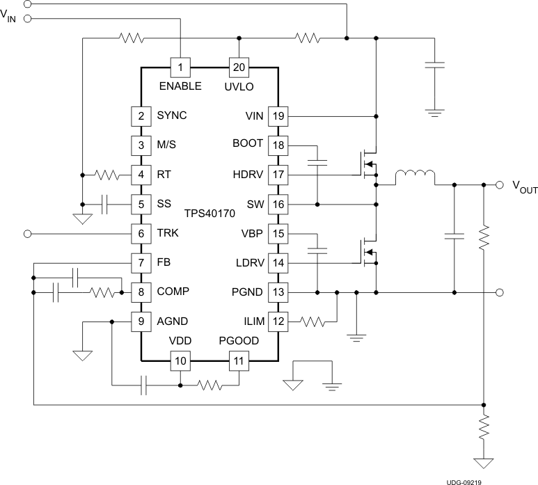
 简化版原理图