ZHCSCQ8D August 2014 – September 2015 LM3644
PRODUCTION DATA.
- 1 特性
- 2 应用
- 3 说明
- 4 修订历史记录
- 5 Device Comparison Table
- 6 Pin Configuration and Functions
- 7 Specifications
-
8 Detailed Description
- 8.1 Overview
- 8.2 Functional Block Diagram
- 8.3 Feature Description
- 8.4 Device Functioning Modes
- 8.5 Programming
- 8.6
Register Descriptions
- 8.6.1 Enable Register (0x01)
- 8.6.2 IVFM Register (0x02)
- 8.6.3 LED1 Flash Brightness Register (0x03)
- 8.6.4 LED2 Flash Brightness Register (0x04)
- 8.6.5 LED1 Torch Brightness Register (0x05)
- 8.6.6 LED2 Torch Brightness Register (0x06)
- 8.6.7 Boost Configuration Register (0x07)
- 8.6.8 Timing Configuration Register (0x08)
- 8.6.9 TEMP Register (0x09)
- 8.6.10 Flags1 Register (0x0A)
- 8.6.11 Flags2 Register (0x0B)
- 8.6.12 Device ID Register (0x0C)
- 8.6.13 Last Flash Register (0x0D)
- 9 Applications and Implementation
- 10Power Supply Recommendations
- 11Layout
- 12器件和文档支持
- 13机械、封装和可订购信息
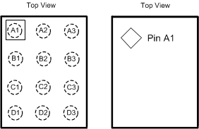
6 Pin Configuration and Functions
YFF Package
12-Pin DSBGA
