ZHCSDJ6E February 2015 – June 2018 LMH1218
PRODUCTION DATA.
- 1 特性
- 2 应用
- 3 说明
- 4 修订历史记录
- 5 Pin Configuration and Functions
- 6 Specifications
-
7 Detailed Description
- 7.1 Overview
- 7.2 Functional Block Diagram
- 7.3
Feature Description
- 7.3.1 Loss of Signal Detector
- 7.3.2 Continuous Time Linear Equalizer (CTLE)
- 7.3.3 2:1 Multiplexer
- 7.3.4 Clock and Data Recovery
- 7.3.5 Eye Opening Monitor (EOM)
- 7.3.6 Fast EOM
- 7.3.7 LMH1218 Device Configuration
- 7.3.8 Power-On Reset
- 7.4 Device Functional Modes
- 7.5 Programming
- 7.6 Register Maps
- 8 Application and Implementation
- 9 Power Supply Recommendations
- 10Layout
- 11器件和文档支持
- 12机械、封装和可订购信息
8.2.1 Design Requirements
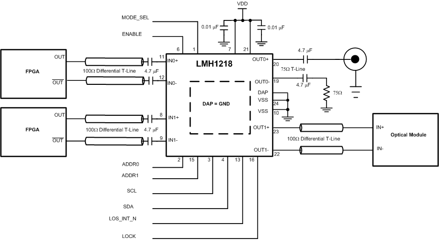
For the LMH1218 design example, the requirements noted in Table 9 apply.
Table 9. LMH1218 Design Parameters
| DESIGN PARAMETER | REQUIREMENT |
|---|---|
| Input AC coupling capacitors | Required. 4.7 µF AC coupling capacitors are recommended. Capacitors may be implemented on the PCB or in the connector. |
| Output AC coupling capacitors | Required. Both OUT0 and OUT1 require AC coupling capacitors. OUT0 AC Coupling capacitors is expected to be 4.7 µF to comply with SMPTE wander requirement. It is assumed that Optical Module has AC coupling capacitors on its input within the module |
| DC Power Supply Coupling Capacitors | To minimize power supply noise, use 0.01 µF capacitors as close to the device VDD pins as possible |
| Distance from Device to BNC | Keep this distance within 1 inch to meet Proposed ST-2081 and ST-2082 requirements |
| High Speed IN0, IN1, OUT0, and OUT1 trace impedance | Design differential trace impedance of IN0, IN1, and OUT1 with 100-Ω ± 5%, single-end trace impedance for OUT0 with 75 Ω ± 5% |
 Figure 24. LMH1218 SMBus Mode Configuration