ZHCSDL7B November 2014 – March 2016 AMC7834
PRODUCTION DATA.
- 1 特性
- 2 应用范围
- 3 说明
- 4 修订历史记录
- 5 Pin Configuration and Functions
-
6 Specifications
- 6.1 Absolute Maximum Ratings
- 6.2 ESD Ratings
- 6.3 Recommended Operating Conditions
- 6.4 Thermal Information
- 6.5 Electrical Characteristics—DAC Specifications
- 6.6 Electrical Characteristics—ADC, Current and Temperature Sensor Specifications
- 6.7 Electrical Characteristics—General Specifications
- 6.8 Serial Interface Timing Requirements
- 6.9 Switching Characteristics—DAC Specifications
- 6.10 Switching Characteristics—ADC, Current and Temperature Sensor Specifications
- 6.11 Switching Characteristics—General Specifications
- 6.12 Typical Characteristics
-
7 Detailed Description
- 7.1 Overview
- 7.2 Functional Block Diagram
- 7.3 Feature Description
- 7.4 Device Functional Modes
- 7.5 Programming
- 7.6
Register Maps
- 7.6.1 Power Mode: Address 0x02
- 7.6.2 Device Identification: Address 0x04 through 0x0C
- 7.6.3
General Device Configuration: Address 0x10 through 0x16
- 7.6.3.1 AMC Configuration 0 Register (address = 0x10) [reset = 0x0300]
- 7.6.3.2 AMC Configuration 1 Register (address = 0x11) [reset = 0x036A]
- 7.6.3.3 ADC MUX Register (address = 0x12) [reset = 0x0000]
- 7.6.3.4 Closed Loop Settling Time Register (address = 0x14) [reset = 0x2222]
- 7.6.3.5 DAC Sync Register (address = 0x15) [reset = 0x0000]
- 7.6.3.6 DAC Range Register (address = 0x16) [reset = 0x0000]
- 7.6.4
Clamp and Alarm Configuration: Address 0x17 through 0x1B
- 7.6.4.1 CLAMP Configuration Register (address = 0x17) [reset = 0x003F]
- 7.6.4.2 SLEEP1 Configuration Register (address = 0x18) [reset = 0xFF00]
- 7.6.4.3 SLEEP2 Configuration Register (address = 0x19) [reset = 0xFF00]
- 7.6.4.4 ALARMOUT Clamp Register (address = 0x1A) [reset = 0x0000]
- 7.6.4.5 ALARMOUT Configuration Register (address = 0x1B) [reset = 0x0000]
- 7.6.5 Conversion Trigger: Address 0x1C
- 7.6.6 Reset: Address 0x1D
- 7.6.7 Device Status: Address 0x1E and 0x1F
- 7.6.8
ADC Data: Address 0x20 through 0x2F
- 7.6.8.1 ADCn-Internal-Data Register (address = 0x20 to 0x23) [reset = 0x0000]
- 7.6.8.2 ADCn-External-Data Register (address = 0x24 to 0x27) [reset = 0x0000]
- 7.6.8.3 CSn-Data Register (address = 0x28 to 0x2B) [reset = 0x0000]
- 7.6.8.4 LT-Data Register (address = 0x2D) [reset = 0x0000]
- 7.6.8.5 RTn-Data Register (address = 0x2E to 0x2F) [reset = 0x0000]
- 7.6.9 DAC Data: Address 0x30 through 0x37
- 7.6.10 Closed-Loop Control: Address 0x38 through 0x3B
- 7.6.11
Alarm Threshold Configuration: Address 0x40 through 0x4F
- 7.6.11.1 ADCINTn/CSn-Upper-Threshold Register (address = 0x40, 0x42, 0x44 and 0x46) [reset = 0x0FFF]
- 7.6.11.2 ADCINTn/CSn-Lower-Threshold Register (address = 0x41, 0x43, 0x45 and 0x47) [reset = 0x0000]
- 7.6.11.3 TS-Upper-Threshold Register (address = 0x48, 0x4A and 0x4C) [reset = 0x07FF]
- 7.6.11.4 TS-Lower-Threshold Register (address = 0x49, 0x4B and 0x4D) [reset = 0x0800]
- 7.6.11.5 DACnn-Upper-Threshold Register (address = 0x4E and 0x4F) [reset = 0x0FFF]
- 7.6.12 Alarm Hysteresis Configuration: Address 0x50 and 0x56
- 7.6.13 GPIO: Address 0x58
- 8 Application and Implementation
- 9 Power Supply Recommendations
- 10Layout
- 11器件和文档支持
- 12机械、封装和可订购信息
10 Layout
10.1 Layout Guidelines
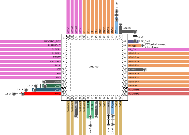
- All power supply pins should be bypassed to ground with a low-ESR ceramic bypass capacitor. The typical recommended bypass capacitance has a value of 0.1 µF and is ceramic with a X7R or NP0 dielectric.
- A 4.7 µF capacitor is recommended between the REF_CMP pin and the AGND4 pin. A minimum capacitor value of 470 nF is required to ensure stability.
- A high-quality ceramic capacitor, type NP0 or X7R, is recommended because of the optimal performance of the capacitor across temperature and very-low dissipation factor.
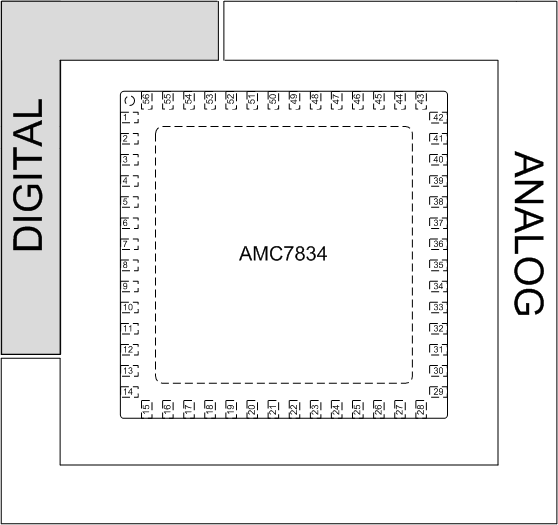
- The digital and analog sections should have proper placement with respect to the digital pins and analog pins of the AMC7834 device (see Figure 110). The separation of analog and digital blocks allows for better design and practice as it ensures less coupling into neighboring blocks and minimizes the interaction between analog and digital return currents.
10.2 Layout Example
 Figure 109. AMC7834 Layout Example
 Figure 110. AMC7834 Example Board Layout — Component Placement