ZHCSEK7D June   2015  – May 2021 LM53600-Q1 , LM53601-Q1

PRODUCTION DATA  

  1. 特性
  2. 应用
  3. 说明
  4. Revision History
  5. Device Comparison
  6. Pin Configuration and Functions
  7. Specifications
    1. 7.1 Absolute Maximum Ratings
    2. 7.2 ESD Ratings
    3. 7.3 Recommended Operating Conditions
    4. 7.4 Thermal Information
    5. 7.5 Electrical Characteristics
    6. 7.6 System Characteristics
    7. 7.7 Timing Requirements
    8. 7.8 Typical Characteristics
  8. Detailed Description
    1. 8.1 Overview
    2. 8.2 Functional Block Diagram
    3. 8.3 Feature Description
      1. 8.3.1 Control Scheme
      2. 8.3.2 Soft-Start Function
      3. 8.3.3 Current Limit
      4. 8.3.4 Hiccup Mode
      5. 8.3.5 RESET Function
      6. 8.3.6 Forced PWM Operation
      7. 8.3.7 Auto Mode Operation and IQ_VIN
      8. 8.3.8 SYNC Operation
      9. 8.3.9 Spread Spectrum
    4. 8.4 Device Functional Modes
      1. 8.4.1 Shutdown
      2. 8.4.2 FPWM Operation
      3. 8.4.3 Auto Mode Operation
  9. Applications and Implementation
    1. 9.1 Application Information
    2. 9.2 Typical Applications
      1. 9.2.1 Off-Battery 5-V, 1-A Output Automotive Converter with Spread Spectrum
        1. 9.2.1.1 Design Requirements
        2. 9.2.1.2 Detailed Design Procedure
          1. 9.2.1.2.1 Inductor Selection
          2. 9.2.1.2.2 Output Capacitor Selection
          3. 9.2.1.2.3 Input Capacitor Selection
          4. 9.2.1.2.4 FB Voltage Divider for Adjustable Versions
          5. 9.2.1.2.5 RPU - RESET Pull Up Resistor
        3. 9.2.1.3 Application Curves
      2. 9.2.2 Off-Battery 3.3 V, 1 A Output Automotive Converter with Spread Spectrum
        1. 9.2.2.1 Design Requirements
        2. 9.2.2.2 Design Procedure
        3. 9.2.2.3 Application Curves
    3. 9.3 Do's and Don't's
  10. 10Power Supply Recommendations
  11. 11Layout
    1. 11.1 Layout Guidelines
      1. 11.1.1 Ground and Thermal Plane Considerations
    2. 11.2 Layout Example
  12. 12Device and Documentation Support
    1. 12.1 Documentation Support
      1. 12.1.1 Related Documentation
    2. 12.2 接收文档更新通知
    3. 12.3 支持资源
    4. 12.4 Trademarks
    5. 12.5 静电放电警告
    6. 12.6 术语表
  13. 13Mechanical, Packaging, and Orderable Information

说明

LM53600-Q1 和 LM53601-Q1 同步降压稳压器器件针对汽车应用进行了优化,能够提供 5V、3.3V 的输出电压或可调输出电压。LM53600-Q1 支持高达 650mA 的负载电流,而 LM53601-Q1 支持高达 1000mA 的负载电流。LM53600-Q1 和 LM53601-Q1 器件可利用高级高速电路在 2.1MHz 的固定频率下实现从 18V 输入到 3.3V 输出的稳压。这两款器件采用创新型架构,在输入电压仅为 3.8V 时也可提供 3.3V 稳压输出。输入电压最高可达 36V,容许的最高瞬态电压达 42V,这简化了输入浪涌保护设计。开漏复位输出具有滤波和延迟释放功能,可提供正确的系统状态指示。凭借这一特性,器件无需使用附加监控元件,这节省了成本和电路板空间。这两款器件可在 PWM 和 PFM 两种模式之间无缝切换,并且静态电流仅为 23µA,这确保了其在所有负载条件下均可展现高效率和出色的瞬态响应。只需很少的外部元件,因此印刷电路板 (PCB) 布局可以更加紧凑。尽管 LM53600-Q1 和 LM53601-Q1 器件属于 Q1 级,但均可在 –40°C 至 150°C 的结温范围内保证电气特性。

器件信息
器件型号 封装(1) 封装尺寸(标称值)
LM53600-Q1 WSON (10) 3.00mm x 3.00mm
LM53601-Q1
如需了解所有可用封装,请参阅数据表末尾的可订购米6体育平台手机版_好二三四附录。
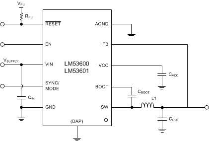
GUID-BF7849EC-2D0E-4779-8F76-1F9614BC6D27-low.gif简化原理图 – 固定输出
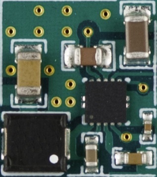
GUID-7678320A-5799-4D1D-B872-ECDA3B94C43E-low.jpg汽车类 11.2mm x 12.7mm 布局