ZHCSEM9 December 2015 TPS92691 , TPS92691-Q1
PRODUCTION DATA.
- 1 特性
- 2 应用
- 3 说明
- 4 修订历史记录
- 5 Pin Configuration and Functions
- 6 Specifications
-
7 Detailed Description
- 7.1 Overview
- 7.2 Functional Block Diagram
- 7.3
Feature Description
- 7.3.1 Internal Regulator and Undervoltage Lockout (UVLO)
- 7.3.2 Oscillator
- 7.3.3 Gate Driver
- 7.3.4 Rail-to-Rail Current Sense Amplifier
- 7.3.5 Transconductance Error Amplifier
- 7.3.6 Switch Current Sense and Internal Slope Compensation
- 7.3.7 Analog Adjust Input
- 7.3.8 PWM Input and Series Dimming FET Gate Driver Output
- 7.3.9 Soft-Start
- 7.3.10 Current Monitor Output
- 7.3.11 Overvoltage Protection
- 7.3.12 Thermal Protection
- 7.4 Device Functional Modes
-
8 Application and Implementation
- 8.1
Application Information
- 8.1.1 Duty Cycle Considerations
- 8.1.2 Inductor Selection
- 8.1.3 Output Capacitor Selection
- 8.1.4 Input Capacitor Selection
- 8.1.5 Main Power MOSFET Selection
- 8.1.6 Rectifier Diode Selection
- 8.1.7 LED Current Programming
- 8.1.8 Switch Current Sense Resistor and Slope Compensation
- 8.1.9 Feedback Compensation
- 8.1.10 Soft-Start
- 8.1.11 Overvoltage Protection
- 8.1.12 PWM Dimming Considerations
- 8.2
Typical Applications
- 8.2.1
Typical Boost LED Driver
- 8.2.1.1 Design Requirements
- 8.2.1.2
Detailed Design Procedure
- 8.2.1.2.1 Calculating Duty Cycle
- 8.2.1.2.2 Setting Switching Frequency
- 8.2.1.2.3 Inductor Selection
- 8.2.1.2.4 Output Capacitor Selection
- 8.2.1.2.5 Input Capacitor Selection
- 8.2.1.2.6 Main N-Channel MOSFET Selection
- 8.2.1.2.7 Rectifying Diode Selection
- 8.2.1.2.8 Programming LED Current
- 8.2.1.2.9 Setting Switch Current Limit and Slope Compensation
- 8.2.1.2.10 Deriving Compensator Parameters
- 8.2.1.2.11 Setting Start-up Duration
- 8.2.1.2.12 Setting Overvoltage Protection Threshold
- 8.2.1.2.13 PWM Dimming Considerations
- 8.2.1.3 Application Curves
- 8.2.2
Typical Buck-Boost LED Driver
- 8.2.2.1 Design Requirements
- 8.2.2.2
Detailed Design Procedure
- 8.2.2.2.1 Calculating Duty Cycle
- 8.2.2.2.2 Setting Switching Frequency
- 8.2.2.2.3 Inductor Selection
- 8.2.2.2.4 Output Capacitor Selection
- 8.2.2.2.5 Input Capacitor Selection
- 8.2.2.2.6 Main N-Channel MOSFET Selection
- 8.2.2.2.7 Rectifier Diode Selection
- 8.2.2.2.8 Setting Switch Current Limit and Slope Compensation
- 8.2.2.2.9 Programming LED Current
- 8.2.2.2.10 Deriving Compensator Parameters
- 8.2.2.2.11 Setting Startup Duration
- 8.2.2.2.12 Setting Overvoltage Protection Threshold
- 8.2.2.2.13 PWM Dimming Consideration
- 8.2.2.3 Application Curves
- 8.2.1
Typical Boost LED Driver
- 8.1
Application Information
- 9 Power Supply Recommendations
- 10Layout
- 11器件和文档支持
- 12机械、封装和可订购信息
1 特性
- 宽输入电压范围:4.5V 至 65V
- 宽输出电压范围:2V 至 65V
- 低输入偏移轨到轨电流感测放大器
- 在 25°C 至 140°C 结温范围内,好于 ±3% 的发光二极管 (LED) 电流精度
- 与高侧和低侧电流感测元件兼容
- 高阻抗模拟 LED 电流调节输入 (IADJ),对比度高于 15:1
- 使用集成的串联 N 通道调光驱动器接口时,具有超过 1000:1 串联场效应管 (FET) 脉宽调制 (PWM) 调光比率
- 具有 LED 电流持续监视输出用于系统故障检测和诊断
- 可编程开关频率以实现与外部时钟同步
- 可编程软启动和斜坡补偿
- 综合故障保护电路,包括电源电压 (VCC) 欠压锁定 (UVLO)、输出过压保护 (OVP)、逐周期开关电流限制和热保护
- TPS92691-Q1:符合汽车类 Q100 1 级标准
2 应用
- TPS92691-Q1:汽车外部照明 应用
- 建筑照明和通用照明 应用
3 说明
TPS92691/-Q1 是一款通用 LED 控制器,支持一系列升压或降压驱动器拓扑。该器件实现了固定频率峰值电流模式控制技术,可编程开关频率、斜坡补偿和软启动时序。其整合了高电压 (65V) 轨到轨电流感测放大器,从而可使用高侧或低侧串联感测电阻直接测量 LED 电流。该放大器可用于实现低输入偏移电压且在 25°C 至 140°C 结温范围和 0 至 60V 输出共模电压范围获得好于 ±3% 的 LED 电流精度。
可使用模拟或 PWM 调光技术单独调制 LED 电流。通过在高阻抗模拟调整输入 (IADJ) 范围内将电压从 140mV 改变为 2.25V 可获得具有 15:1 范围的线性模拟调光响应。通过将 PWM 输入引脚调制为所需的占空比和频率实现 LED 电流的 PWM 调光。可使用可选 DDRV 栅极驱动器输出使串联 FET 调光功能获得高于 1000:1 的对比度。
TPS92691/-Q1 支持通过电流监视输出连续检查 LED 状态。这样就可以实现 LED 短路或开路检测和保护。其他故障保护 特性 包括 VCC UVLO、输出过压保护 (OVP)、开关逐周期电流限制和热保护。
器件信息(1)
| 器件型号 | 封装 | 封装尺寸(标称值) |
|---|---|---|
| TPS92691-Q1 TPS92691 |
HTSSOP (16) | 5.10mm x 6.60mm |
- 要了解所有可用封装,请参见数据表末尾的可订购米6体育平台手机版_好二三四附录。
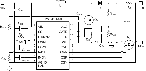
典型升压 LED 驱动器应用原理图

效率与输出电压之间的关系
