ZHCSFF5G July 2016 – December 2019 TPS2660
PRODUCTION DATA.
- 1 特性
- 2 应用
- 3 说明
- 4 修订历史记录
- 5 Device Comparison Table
- 6 Pin Configuration and Functions
- 7 Specifications
- 8 Parameter Measurement Information
-
9 Detailed Description
- 9.1 Overview
- 9.2 Functional Block Diagram
- 9.3
Feature Description
- 9.3.1 Undervoltage Lockout (UVLO)
- 9.3.2 Overvoltage Protection (OVP)
- 9.3.3 Reverse Input Supply Protection
- 9.3.4 Hot Plug-In and In-Rush Current Control
- 9.3.5 Overload and Short Circuit Protection
- 9.4 Device Functional Modes
-
10Application and Implementation
- 10.1 Application Information
- 10.2
Typical Application
- 10.2.1 Design Requirements
- 10.2.2 Detailed Design Procedure
- 10.2.3 Application Curves
- 10.3 System Examples
- 10.4 Do's and Don'ts
- 11Power Supply Recommendations
- 12Layout
- 13器件和文档支持
- 14机械、封装和可订购信息
10.3.1 Acive ORing Operation
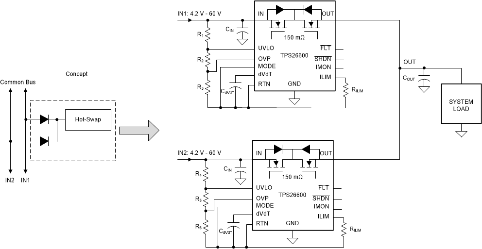
 Figure 64. Active ORing Application Schematic
 Figure 64 shows a typical redundant power supply configuration of the system. Schottky ORing diodes have been popular for connecting parallel power supplies, such as parallel operation of wall adapter with a battery or a hold-up storage capacitor. The disadvantage of using ORing diodes is high voltage drop and associated power loss. The TPS2660x with integrated, N-channel back to back FETs provide a simple and efficient solution.
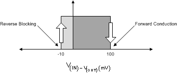
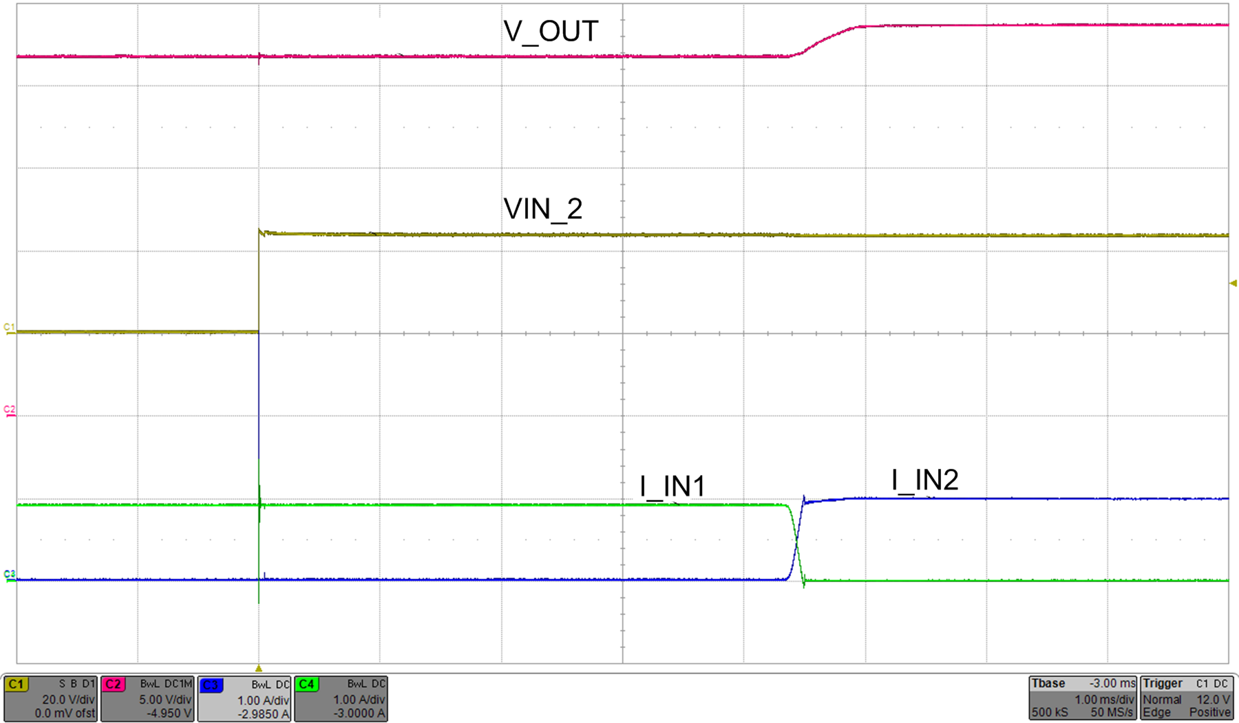
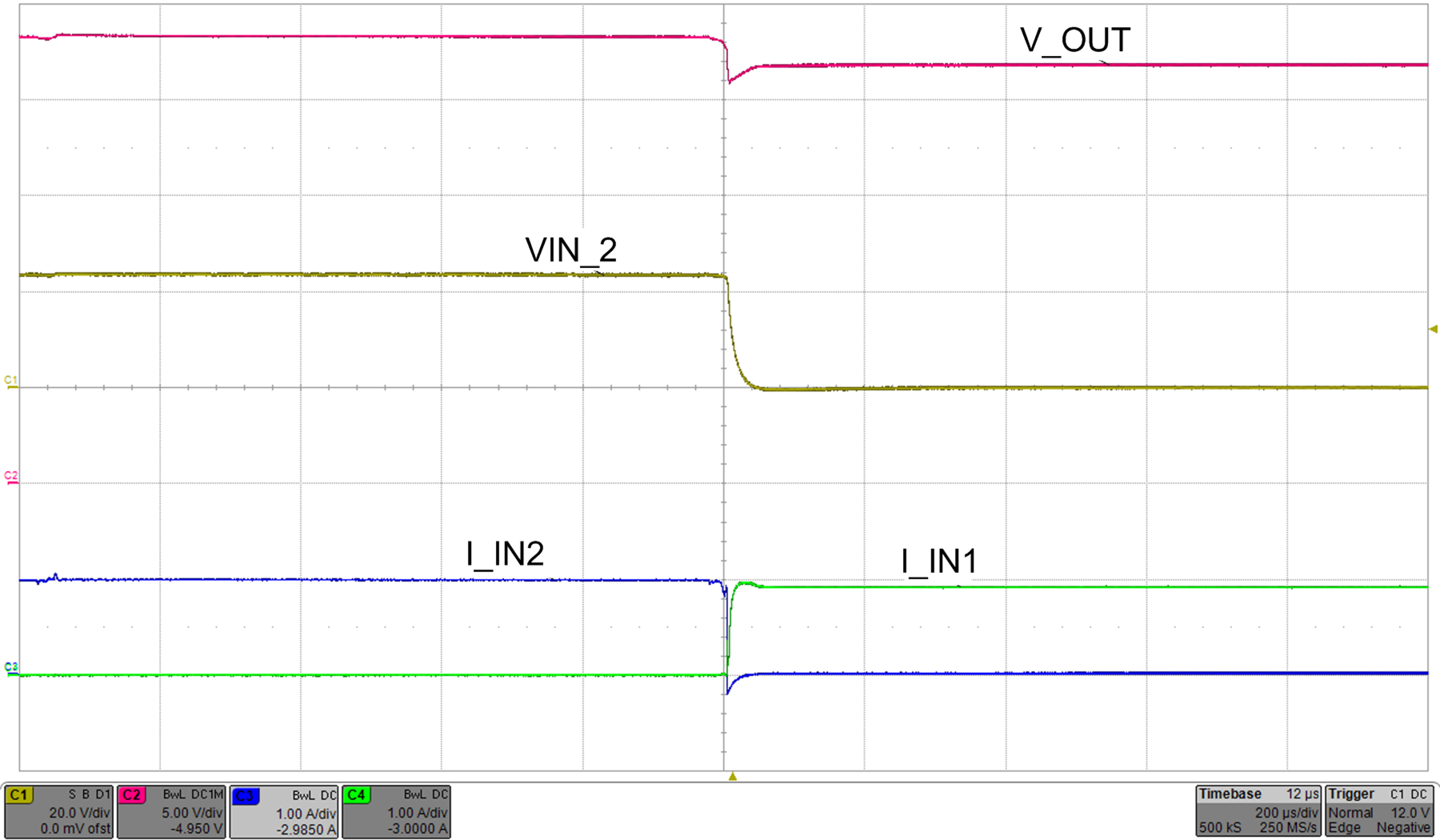
A fast reverse comparator controls the internal FET and it is turned ON or OFF with hysteresis as shown in Figure 65. The internal FET is turned off within 1.5 μs (typical) as soon as V(IN) – V(OUT) falls below –110 mV. It turns on within 40 µs (typical) once the differential forward voltage V(IN) – V(OUT) exceeds 100 mV. Figure 66 and Figure 67 show typical switch-over waveforms of Active ORing implementation using the TPS26600.
 Figure 65. Active ORing Thresholds
| VIN1 = 22 V | Cout = 47 μF | Rload = 24 Ω |
| VIN2: Plugged In at 24 V | C(dVdT) = 22 nF |

| VIN1 = 22 V | Cout = 47 μF | Rload = 24 Ω |
| VIN2: Plugged Out | C(dVdT) = 22 nF |
NOTE
All control pins of the un-powered TPS2660x device in the Active ORing configuration will measure approximately 0.7 V drop with respect to GND. The system micro-controller should ignore IMON and FLT pin voltage measurements of this device when these signals are being monitored.