ZHCSFV6E august 2016 – november 2020 DS90UB933-Q1
PRODUCTION DATA
- 1
- 1 特性
- 2 应用
- 3 说明
- 4 Revision History
- 5 Pin Configuration and Functions
-
6 Specifications
- 6.1 Absolute Maximum Ratings
- 6.2 ESD Ratings
- 6.3 Recommended Operating Conditions
- 6.4 Thermal Information
- 6.5 Electrical Characteristics
- 6.6 Recommended Serializer Timing For PCLK
- 6.7 AC Timing Specifications (SCL, SDA) - I2C-Compatible
- 6.8 Bidirectional Control Bus DC Timing Specifications (SCL, SDA) - I2C-Compatible
- 6.9 Serializer Switching Characteristics
- 6.10 Timing Diagrams
- 6.11 Typical Characteristics
- 7 Detailed Description
- 8 Application and Implementation
- 9 Power Supply Recommendations
- 10Layout
- 11Device and Documentation Support
7.4.3 MODE Pin on Serializer
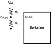
The MODE pin on the serializer can be configured to select if the DS90UB933-Q1 device is to be operated from the external oscillator or the PCLK from the imager. The pin must be pulled to VDD_n(1.8 V, not VDDIO) with a resistor R1 and a pulldown resistor R2 for external oscillator mode to create the ratio shown in Figure 7-6. If the device is to be operated from PCLK from imager mode, MODE pin can be pulled up to VDD_n (1.8V) with a 10-kΩ resistor directly or use the ratio shown in Figure 7-6 and Table 7-2. Suggested resistor values are given in Table 7-2. The recommended maximum resistor tolerance is 1%. Other resistor values can be used as long as the ratio is met under all conditions.
 Figure 7-6 MODE Pin Configuration on DS90UB933-Q1
MODE Setting
| DS90UB933-Q1 SERIALIZER MODE SETTING | ||||
|---|---|---|---|---|
| MODE SELECT | MINIMUM RATIO (VMODE/V(VDD_n)) | MAXIMUM RATIO (VMODE/V(VDD_n)) | SUGGESTED R1 RESISTOR VALUE (kΩ) | SUGGESTED R2 RESISTOR VALUE (kΩ) |
| PCLK from imager mode | 0.750 | 1.000 | 10 | 50 |
| External oscillator mode | 0.292 | 0.339 | 10 | 4.7 |