ZHCSGQ0A September   2017  – February 2022 TIC10024-Q1

PRODUCTION DATA  

  1. 特性
  2. 应用
  3. 说明
  4. Revision History
  5. Pin Configuration and Functions
  6. Specifications
    1. 6.1 Absolute Maximum Ratings
    2. 6.2 ESD Ratings
    3. 6.3 Recommended Operating Conditions
    4. 6.4 Thermal Information
    5. 6.5 Electrical Characteristics
    6. 6.6 Timing Requirements
    7. 6.7 Typical Characteristics
  7. Parameter Measurement Information
  8. Detailed Description
    1. 8.1 Overview
    2. 8.2 Functional Block Diagram
    3. 8.3 Feature Description
      1. 8.3.1  VS Pin
      2. 8.3.2  VDD Pin
      3. 8.3.3  Device Initialization
      4. 8.3.4  Device Trigger
      5. 8.3.5  Device Reset
        1. 8.3.5.1 VS Supply POR
        2. 8.3.5.2 Hardware Reset
        3. 8.3.5.3 Software Reset
      6. 8.3.6  VS Under-Voltage (UV) Condition
      7. 8.3.7  VS Over-Voltage (OV) Condition
      8. 8.3.8  Switch Inputs Settings
        1. 8.3.8.1 Input Current Source and Sink Selection
        2. 8.3.8.2 Input Enable Selection
        3. 8.3.8.3 Thresholds Adjustment
        4. 8.3.8.4 Wetting Current Configuration
      9. 8.3.9  Interrupt Generation and INT Assertion
        1. 8.3.9.1 INT Pin Assertion Scheme
        2. 8.3.9.2 Interrupt Idle Time (tINT_IDLE) Time
        3. 8.3.9.3 Microcontroller Wake-Up
        4. 8.3.9.4 Interrupt Enable / Disable And Interrupt Generation Conditions
        5. 8.3.9.5 Detection Filter
      10. 8.3.10 Temperature Monitor
        1. 8.3.10.1 Temperature Warning (TW)
        2. 8.3.10.2 Temperature Shutdown (TSD)
      11. 8.3.11 Parity Check And Parity Generation
      12. 8.3.12 Cyclic Redundancy Check (CRC)
    4. 8.4 Device Functional Modes
      1. 8.4.1 Continuous Mode
      2. 8.4.2 Polling Mode
      3. 8.4.3 Additional Features
        1. 8.4.3.1 Clean Current Polling (CCP)
        2. 8.4.3.2 Wetting Current Auto-Scaling
  9. Programming
    1. 9.1 SPI Communication Interface Buses
      1. 9.1.1 Chip Select ( CS)
      2. 9.1.2 System Clock (SCLK)
      3. 9.1.3 Slave In (SI)
      4. 9.1.4 Slave Out (SO)
    2. 9.2 SPI Sequence
      1. 9.2.1 Read Operation
      2. 9.2.2 Write Operation
      3. 9.2.3 Status Flag
    3. 9.3 Programming Guidelines
    4. 9.4 Register Maps
  10. 10Application and Implementation
    1. 10.1 Application Information
    2. 10.2 Digital Switch Detection in Automotive Body Control Module
      1. 10.2.1 Design Requirements
      2. 10.2.2 Detailed Design Procedure
      3. 10.2.3 Application Curves
    3. 10.3 Systems Examples
      1. 10.3.1 Using TIC10024-Q1 in a 12 V Automotive System
  11. 11Power Supply Recommendations
  12. 12Layout
    1. 12.1 Layout Guidelines
    2. 12.2 Layout Example
  13. 13Device and Documentation Support
    1. 13.1 Receiving Notification of Documentation Updates
    2. 13.2 Community Resources
    3. 13.3 Trademarks
  14. 14Mechanical, Packaging, and Orderable Information

说明

TIC10024-Q1 是一款先进的多开关检测接口 (MSDI) 器件,用于检测 12V 汽车系统中的外部开关状态。TIC10024-Q1 配有可调阈值的比较器,可以独立于 MCU 的方式监控数字开关。该器件监控多达 24 路直接开关输入,并可配置其中 10 路输入以监控接地或连接到电池的开关。可为每路输入设定 6 种独特的湿性电流设置,从而支持不同的应用场景。该器件支持所有开关输入的唤醒操作,因此无需持续使 MCU 保持活动状态,进而可降低系统功耗。TIC10024-Q1 还提供集成故障检测和 ESD 保护功能,从而提高系统稳健性。TIC10024-Q1 支持 2 种工作模式:连续模式和轮询模式。连续模式下将连续提供湿性电流。轮询模式下将根据可编程计时器来定期接通湿性电流以对输入状态进行采样,从而显著降低系统功耗。

器件信息
器件型号封装(1)封装尺寸(标称值)
TIC10024-Q1TSSOP (38)9.70 mm x 4.40 mm
如需了解所有可用封装,请参阅数据表末尾的可订购米6体育平台手机版_好二三四附录。
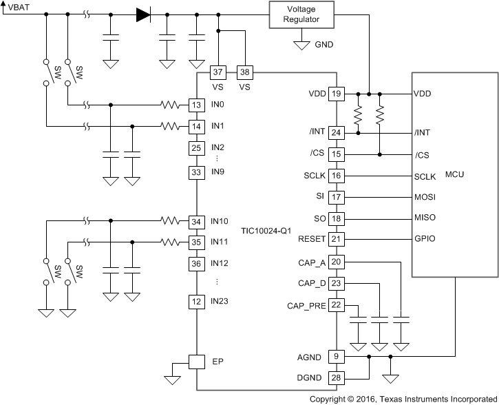
GUID-80B5F99F-7D01-4BD3-B5AA-C8AF0EBFFAC6-low.gif简化版原理图