ZHCSGV7F July 2017 – January 2024 CDCI6214
PRODUCTION DATA
- 1
- 1 特性
- 2 应用
- 3 说明
- 4 Device Comparison
- 5 Pin Configuration and Functions
-
6 Specifications
- 6.1 Absolute Maximum Ratings
- 6.2 ESD Ratings
- 6.3 Recommended Operating Conditions
- 6.4 Thermal Information
- 6.5 EEPROM Characteristics
- 6.6 Reference Input, Single-Ended and Differential Mode Characteristics (REFP, REFN, FB_P, FB_N)
- 6.7 Reference Input, Crystal Mode Characteristics (XIN, XOUT)
- 6.8 General-Purpose Input and Output Characteristics (GPIO[4:1], SYNC/RESETN)
- 6.9 Triple Level Input Characteristics (EEPROMSEL, REFSEL)
- 6.10 Reference Mux Characteristics
- 6.11 Phase-Locked Loop Characteristics
- 6.12 Closed-Loop Output Jitter Characteristics
- 6.13 Output Mux Characteristics
- 6.14 LVCMOS Output Characteristics
- 6.15 HCSL Output Characteristics
- 6.16 LVDS DC-Coupled Output Characteristics
- 6.17 Programmable Differential AC-Coupled Output Characteristics
- 6.18 Output Skew and Delay Characteristics
- 6.19 Output Synchronization Characteristics
- 6.20 Timing Characteristics
- 6.21 I2C-Compatible Serial Interface Characteristics (SDA/GPIO2, SCL/GPIO3)
- 6.22 Timing Requirements, I2C-Compatible Serial Interface (SDA/GPIO2, SCL/GPIO3)
- 6.23 Power Supply Characteristics
- 6.24 Typical Characteristics
- 7 Parameter Measurement Information
-
8 Detailed Description
- 8.1 Overview
- 8.2 Functional Block Diagram
- 8.3 Feature Description
- 8.4 Device Functional Modes
- 8.5 Programming
- 9 Application and Implementation
- 10Register Maps
- 11Device and Documentation Support
- 12Revision History
- 13Mechanical, Packaging, and Orderable Information
3 说明
CDCI6214 器件是一款超低功耗时钟发生器。此器件在锁相环的两个独立基准输入之间进行选择,并在可配置的差分输出通道上产生多达四个不同的频率,还在 LVCMOS 输出通道上生成参考时钟。
四个输出通道中的每个通道都有一个可配置的整数分频器。通过与输出多路复用器结合,这样可产生五种不同的频率。时钟分配分频器通过确定性方式进行复位,以便实现干净的时钟门控以及无毛刺更新功能。可通过灵活的断电选项优化器件以便在工作和待机模式中实现最低功耗。通常,四路 156.25MHz LVDS 输出在 1.8V 时的功耗为 150mW。100MHz HCSL 输出的典型 RMS 抖动为 386fs,可提高 PCIe 应用的系统裕度。
CDCI6214 由内部寄存器进行配置。可通过与 I2C 兼容的串行接口和内部 EEPROM 访问这些寄存器。
CDCI6214 采用小型封装并具有超低功耗,可根据单个基准实现高性能时钟树。CDCI6214 具有工厂和用户可编程的 EEPROM,该时钟特性方便易用,可瞬时启动,并能实现低功耗。
(1) 有关所有可选封装,请参阅 节 13。
(2) 四路 LVDS 输出,156.25MHz(含晶振参考)。
(3) 封装尺寸(长 × 宽)为标称值,并包括引脚(如适用)。
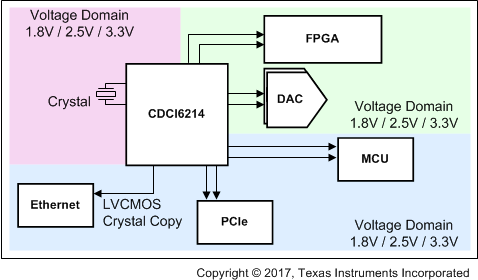
 CDCI6214 应用示例