ZHCSGY7B October 2017 – January 2018 TPS92830-Q1
PRODUCTION DATA.
- 1 特性
- 2 应用
- 3 说明
- 4 修订历史记录
- 5 说明 (续)
- 6 Pin Configuration and Functions
- 7 Specifications
- 8 Detailed Description
- 9 Application and Implementation
- 10Layout
- 11器件和文档支持
- 12机械、封装和可订购信息
8.3.5.1 Analog Dimming Topology
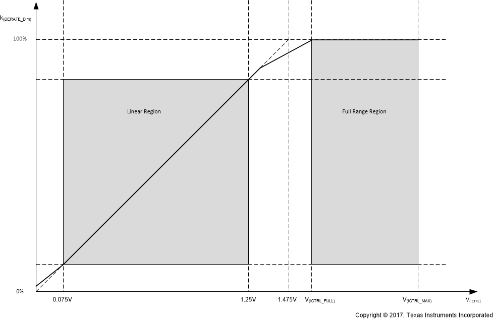
Voltage at the ICTRL pin, V(ICTRL), is used for analog dimming control. To set V(ICTRL), either a reference input voltage can be applied or a resistor between ICTRL and GND can be used.
When V(ICTRL) is greater than V(ICTRL_FULL), analog dimming is not enabled; thus the analog dimming ratio is at 100%.
When V(ICTRL) is between V(ICTRL_LIN_BOT) and V(ICTRL_LIN_TOP), the analog dimming ratio is directly proportional to V(ICTRL). The analog dimming ratio can be calculated using the following equation. V(ICTRL_LIN_BOT) and V(ICTRL_LIN_TOP) represent the ICTRL voltage boundaries of the linear region.

When VICTRL is between V(ICTRL_LIN_TOP) and V(ICTRL_FULL) or between V(ICTRL_LIN_BOT) and 0, analog dimming is in a transition region, and linearity is not assured. Thus it is not recommended to use ICTRL in these regions.
 Figure 26. Analog Dimming Ratio