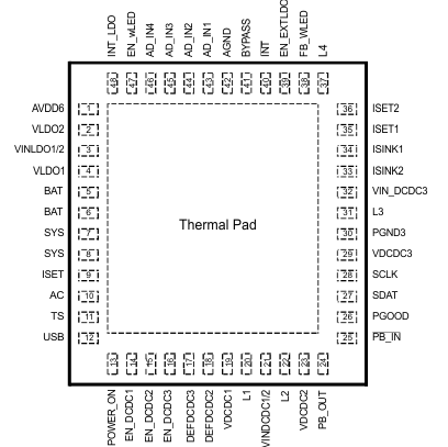
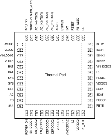
| CHARGER BLOCK |
| AC |
10 |
10 |
I |
Input power for power path manager, connect to external DC supply. Connect external 1 µF (minimum) to GND |
| AD_IN1 (TSX1) |
43 |
43 |
I |
Analog input1 for A/D converter;
TPS65070, TPS65073, TPS650731, TPS650732 only:
Input 1 to the x-plate for the touch screen. |
| AD_IN2 (TSX2) |
44 |
44 |
I |
Analog input2 for A/D converter;
TPS65070, TPS65073, TPS650731, TPS650732 only:
Input 2 to the x-plate for the touch screen |
| AD_IN3 (TSY1) |
45 |
45 |
I |
Analog input3 for A/D converter;
TPS65070, TPS65073, TPS650731, TPS650732 only:
Input 1 to the y-plate for the touch screen |
| AD_IN4 (TSY2) |
46 |
46 |
I |
Analog input4 for A/D converter;
TPS65070, TPS65073, TPS650731, TPS650732 only:
Input 2 to the y-plate for the touch screen |
| AVDD6 |
1 |
1 |
O |
Internal “always-on”-voltage. Connect a 4.7-µF capacitor from AVDD6 to GND |
| BAT |
5, 6 |
5, 6 |
O |
Charger power stage output, connect to battery. Place a ceramic capacitor of 10 µF from these pins to GND |
| BYPASS |
41 |
41 |
O |
Connect a 10-µF bypass capacitor from this pin to GND. This pin can optionally be used as a reference output (2.26 V). The maximum load on this pin is 0.1 mA. |
| INT |
40 |
40 |
O |
Open-drain interrupt output. An interrupt can be generated upon:
• A touch of the touch screen
• Voltage applied or removed at pins AC or USB
• PB_IN actively pulled low (optionally actively pulled high) |
| INT_LDO |
48 |
48 |
O |
Connect a 2.2-µF bypass capacitor from this pin to GND. The pin is connected to an internal LDO providing the power for the touch screen controller (TSREF). |
| ISET |
9 |
9 |
I |
Connect a resistor from ISET to GND to set the charge current. |
| SCLK |
28 |
28 |
I |
Clock input for the I2C interface. |
| SDAT |
27 |
27 |
I/O |
Data line for the I2C interface. |
| SYS |
7, 8 |
7, 8 |
O |
System voltage; output of the power path manager. All voltage regulators are typically powered from this output. |
| TS |
11 |
11 |
I |
Temperature sense input. Connect to NTC thermistor to sense battery pack temperature. TPS6507x can be internally programmed to operate with a 10-kΩ curve 2 or 100-kΩ curve 1 thermistor. To linearize the thermistor response, use a 75-kΩ (for the 10-kΩ NTC) or a 360-kΩ (for the 100-kΩ NTC) in parallel with the thermistor. Default setting is 10-kΩ NTC. |
| USB |
12 |
12 |
I |
Input power for power path manager, connect to external voltage from a USB port. Connect external 1 µF (minimum) to GND. Default input current limit is 500 mA maximum. |
| CONVERTERS |
| AGND |
42 |
42 |
— |
Analog GND, connect to PGND (thermal pad) |
| DEFDCDC2 |
18 |
18 |
I |
Select Pin of DCDC2 output voltage. |
| DEFDCDC3 |
17 |
17 |
I |
Select Pin of DCDC3 output voltage. |
| EN_DCDC1 |
14 |
14 |
I |
Enable Input for DCDC1, active high |
| EN_DCDC2 |
15 |
15 |
I |
Enable Input for DCDC2, active high |
| EN_DCDC3 |
16 |
16 |
I |
Enable Input for DCDC3, active high |
| EN_EXTLDO |
— |
39 |
O |
TPS65072:
This pin is the active high, push-pull output to enable an external LDO. This pin will be set and reset during startup and shutdown by the sequencing option programmed. The output is pulled internally to the SYS voltage if HIGH.
The output is only used for sequencing options for Sirf Prima or Atlas 4 processors with DCDC_SQ[2..0] = 100 or DCDC_SQ[2..0] = 111. |
| EN_wLED |
— |
47 |
I |
TPS65072, : This pin is the actively high enable input for the wLED driver. The wLED converter is enabled by the ENABLE ISINK Bit OR enable EN_wLED pin. |
| FB_WLED |
38 |
38 |
I |
Feedback input for the boost converter's output voltage. |
ISET1
(AD_IN6) |
35 |
35 |
I |
Connect a resistor from this pin to GND to set the full scale current for Isink1 and Isink2 with Bit Current Level in register WLED_CTRL0 set to 1.
Analog input6 for the A/D converter. |
ISET2
(AD_IN7) |
36 |
36 |
I |
Connect a resistor from this pin to GND to set the full scale current for Isink1 and Isink2 with Bit Current Level in register WLED_CTRL0 set to 0.
Analog input7 for the A/D converter. |
| ISINK1 |
34 |
34 |
I |
Input to the current sink 1. Connect the cathode of the LEDs to this pin. |
| ISINK2 |
33 |
33 |
I |
Input to the current sink 2. Connect the cathode of the LEDs to this pin. |
| L1 |
20 |
20 |
O |
Switch Pin for DCDC1. Connect to Inductor |
| L2 |
22 |
22 |
O |
Switch Pin of DCDC2. Connect to Inductor. |
| L3 |
31 |
31 |
O |
Switch Pin of DCDC3. Connect to Inductor. |
| L4 |
37 |
37 |
I |
Switch Pin of the white LED (wLED) boost converter. Connect to Inductor and rectifier diode. |
| PB_IN |
25 |
25 |
I |
Enable input for TPS6507x. When pulled LOW, the DCDC converters and LDOs start with the sequencing as programmed internally. Internal 50kO pullup resistor to AVDD6 |
| PB_OUT |
24 |
24 |
O |
Open-drain output. This pin is driven by the status of the /PB_IN input (after debounce). PB_OUT=LOW if PB_IN=LOW |
| PGND3 |
30 |
30 |
— |
Power GND for DCDC3. Connect to PGND (thermal pad) |
| PGOOD |
26 |
26 |
O |
Open-drain power good output. The delay time equals the setting for Reset. The pin will go low depending on the setting in register PGOODMASK. Optionally it is also driven LOW for 0.5 ms when PB_IN is pulled LOW for >15s. |
| POWER_ON |
13 |
13 |
I |
Power_ON input for the internal state machine. After PB_IN was pulled LOW to turn on the TPS6507x, the POWER_ON pin needs to be pulled HIGH by the application processor to keep the system in ON-state when PB_IN is released HIGH. If POWER_ON is released LOW, the DCDC converters and LDOs will turn off when PB_IN is HIGH. |
| RESET |
39 |
— |
O |
TPS65070, TPS65073, TPS650731, TPS650732:
Open-drain active low reset output, reset delay time equals settings in register PGOOD. The status depends on the voltage applied at THRESHOLD. |
| THRESHOLD |
47 |
— |
I |
TPS65070, TPS65073, TPS650731, TPS650732:Input for the reset comparator. RESET will be LOW if this voltage drops below 1 V. |
| VDCDC1 |
19 |
19 |
I |
Feedback voltage sense input. For the fixed voltage option, this pin must directly be connected to Vout1, for the adjustable version, this pin is connected to an external resistor divider. |
| VDCDC2 |
23 |
23 |
I |
Feedback voltage sense input, connect directly to Vout2 |
| VDCDC3 |
29 |
29 |
I |
Feedback voltage sense input, connect directly to Vout3 |
| VINDCDC1/2 |
21 |
21 |
I |
Input voltage for DCDC1 and DCDC2 step-down converter. This pin must be connected to the SYS pin. |
| VINLDO1/2 |
3 |
3 |
I |
Input voltage for LDO1 and LDO2 |
| VIN_DCDC3 |
32 |
32 |
I |
Input voltage for DCDC3 step-down converter. This pin must be connected to the SYS pin. |
| VLDO1 |
4 |
4 |
O |
Output voltage of LDO1 |
| VLDO2 |
2 |
2 |
O |
Output voltage of LDO2 |
| Thermal Pad |
— |
Power ground connection for the PMU. Connect to GND |

