ZHCSIA5A July 2018 – December 2018 INA253
PRODUCTION DATA.
- 1 特性
- 2 应用
- 3 说明
- 4 修订历史记录
- 5 Device Comparison Table
- 6 Pin Configuration and Functions
- 7 Specifications
-
8 Detailed Description
- 8.1 Overview
- 8.2 Functional Block Diagram
- 8.3 Feature Description
- 8.4
Device Functional Modes
- 8.4.1 Adjusting the Output Midpoint With the Reference Pins
- 8.4.2 Reference Pin Connections for Unidirectional Current Measurements
- 8.4.3 Ground Referenced Output
- 8.4.4 Reference Pin Connections for Bidirectional Current Measurements
- 8.4.5 Output Set to Mid-Supply Voltage
- 8.4.6 Output Set to Mid-External Reference
- 8.4.7 Output Set Using Resistor Divide
- 9 Application and Implementation
- 10Power Supply Recommendations
- 11Layout
- 12器件和文档支持
- 13机械、封装和可订购信息
8.3.3 Temperature Stability
System calibration is common for many industrial applications in order to eliminate initial component and system-level errors that can be present. A system-level calibration reduces the initial accuracy requirement for many of the individual components because the errors associated with these components are effectively eliminated through the calibration procedure. This calibration enables precise measurements at the temperature in which the system is calibrated. As the system temperature changes because of external ambient changes or self heating, measurement errors are reintroduced. Without accurate temperature compensation used in addition to the initial adjustment, the calibration procedure is not effective. The user must account for temperature-induced changes. One of the primary benefits of the low temperature coefficient of the INA253 (including both the integrated current-sensing resistor and current-sensing amplifier) is that the device measurement remains accurate, even when the temperature changes throughout the specified temperature range of the device.
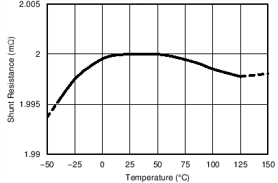
Figure 31 shows the drift performance for the integrated current-sensing resistor. Use Figure 31 to determine the typical variance in the shunt resistor value at various temperatures. As with any resistive element, the tolerance of the component varies when exposed to different temperature conditions. For the current-sensing resistor integrated in the INA253, the resistor does vary slightly more when operated in temperatures ranging from –40°C to 0°C than when operated from 0°C to 125°C. Even in the –40°C to 0°C temperature range, the drift is still low at 25 ppm/°C.
 Figure 31. Sensing Resistor vs Temperature
 An additional aspect to consider is that when current flows through the current-sensing resistor, power is dissipated across this component. This dissipated power results in an increase in the internal temperature of the package, including the integrated sensing resistor. This resistor self-heating effect results in an increase of the resistor temperature helping to move the component out of the colder, wider drift temperature region.