ZHCSIN9A August 2018 – November 2018 ADS1119
PRODUCTION DATA.
- 1 特性
- 2 应用
- 3 说明
- 4 修订历史记录
- 5 Pin Configuration and Functions
- 6 Specifications
- 7 Parameter Measurement Information
- 8 Detailed Description
- 9 Application and Implementation
- 10Power Supply Recommendations
- 11Layout
- 12器件和文档支持
- 13机械、封装和可订购信息
9.1.1 Interface Connections
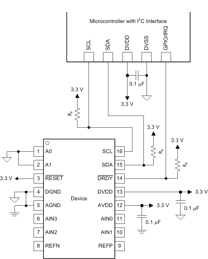
Figure 43 shows the principle interface connections for the ADS1119.
 Figure 43. Interface Connections
 The ADS1119 interfaces directly to standard-mode, fast-mode, or fast-mode plus I2C controllers. Any microcontroller I2C peripheral, including master-only and single-master I2C peripherals, operates with the ADS1119. Details of the I2C communication protocol of the device can be found in the Programming section. The ADS1119 does not perform clock-stretching (that is, the device never pulls the clock line low), so this function does not need to be provided for unless other clock-stretching devices are present on the same I2C bus.
Pullup resistors are required on both the SDA and SCL lines, as well as on the open-drain DRDY output. The size of these resistors depends on the bus operating speed and capacitance of the bus lines. Higher-value resistors yield lower power consumption when the bus lines are pulled low, but increase the transition times on the bus, which limits the bus speed. Lower-value resistors allow higher interface speeds, but at the expense of higher power consumption when the bus lines are pulled low. Long bus lines have higher capacitance and require smaller pullup resistors to compensate. Do not use resistors that are too small because the bus drivers may be unable to pull the bus lines low. See the I2C-Bus Specification and User Manual for details on pullup resistor sizing.