ZHCSJ60D November 2018 – December 2019 TPS1HA08-Q1
PRODUCTION DATA.
- 1 特性
- 2 应用
- 3 说明
- 4 修订历史记录
- 5 Device Comparison Table
- 6 Pin Configuration and Functions
- 7 Specifications
- 8 Parameter Measurement Information
-
9 Detailed Description
- 9.1 Overview
- 9.2 Functional Block Diagram
- 9.3
Feature Description
- 9.3.1 Protection Mechanisms
- 9.3.2 Diagnostic Mechanisms
- 9.3.3 Enable Watchdog
- 9.4 Device Functional Modes
- 10Application and Implementation
- 11Power Supply Recommendations
- 12Layout
- 13器件和文档支持
- 14机械、封装和可订购信息
9.3.1.6 Fault Event – Timing Diagrams
NOTE
All timing diagrams assume that the SELx pins are set to 00.
The LATCH, DIA_EN, and EN pins are controlled by the user. The timing diagrams represent a possible use-case.
Figure 42 shows the immediate current limit switch off behavior of Versions A,B,E. The diagram also illustrates the retry behavior. As shown, the switch will remain latched off until the LATCH pin is low.
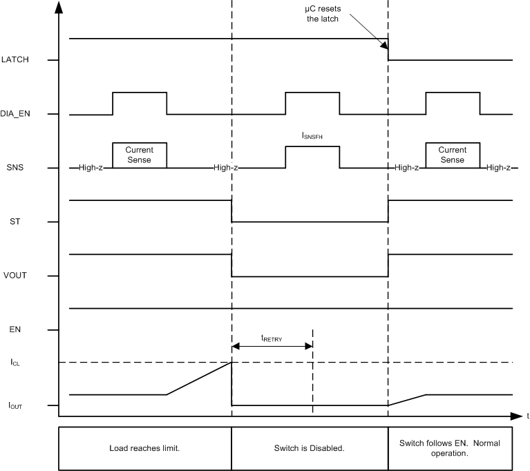 Figure 42. Current Limit – Version A,B,E - Latched Behavior
 Figure 43 shows the immediate current limit switch off behavior of versions A,B,E. In this example, LATCH is tied to GND; hence, the switch will retry after the fault is cleared and tRETRY has expired.
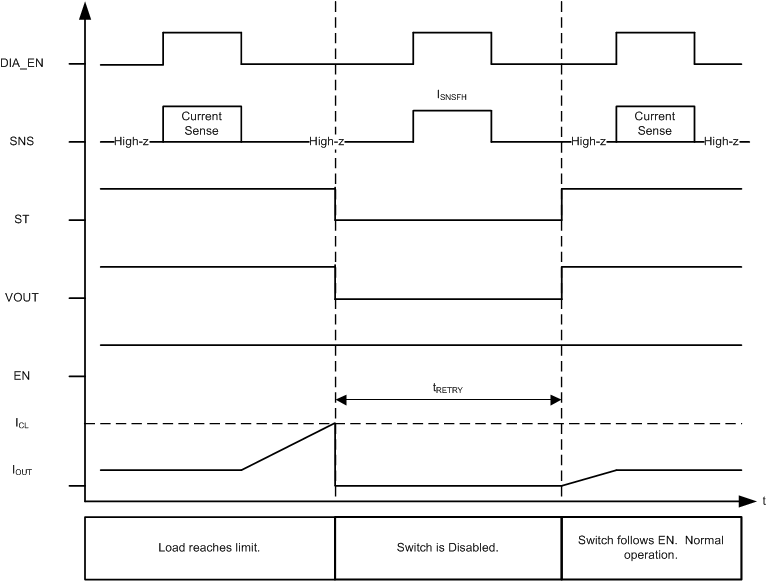 Figure 43. Current Limit – Version A,B,E - LATCH = 0
 Figure 44 shows the active current limiting behavior of versions C,D. In versions C,D, the switch will not shutdown until either the energy limit or the thermal shutdown is reached.
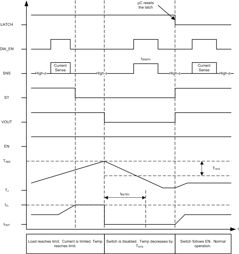 Figure 44. Current Limit – Version C,D - Latched Behavior
 Figure 45 shows the active current limiting behavior of versions C,D. The switch will not shutdown until either thermal shutdown or energy limit is tripped. In this example, LATCH is tied to GND.
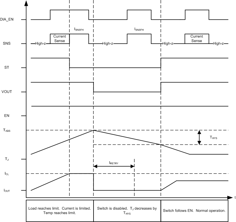 Figure 45. Current Limit – Version C,D - LATCH = 0
 When the switch retries after a shutdown event, the SNS fault indication will remain until VOUT has risen to VBB – 1.8 V. Once VOUT has risen, the SNS fault indication is reset and current sensing is available. ST fault indication is reset as soon as the switch is re-enabled (does not wait for VOUT to rise). If there is a short-to-ground and VOUT is not able to rise, the SNS fault indication will remain indefinitely. The following diagram illustrates auto-retry behavior and provides a zoomed-in view of the fault indication during retry.
NOTE
Figure 46 assumes that tRETRY has expired by the time that TJ reaches the hysteresis threshold.
LATCH = 0 V and DIA_EN = 5 V
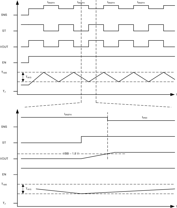 Figure 46. Fault Indication During Retry