ZHCSJL9B April 2019 – April 2019 TPS566235
PRODUCTION DATA.
7.4.2 MODE Pin Configuration
TPS566235 detect the voltage on the MODE pin during start-up and latches onto one of the MODE options listed below in Table 1. TPS566235 internally has a comparator to compare this voltage with reference voltage and decide which mode to choose. The voltage on the MODE pin can be set by connecting to VCC pin or connecting a resistor RM between this pin and AGND. There is a source current of 5 µA at the mode pin and generate voltage for mode selection to avoid noise and spurious trigger. The VMODE voltage range and recommended resistor value is shown in Table 1. The MODE pin setting can be reset only by VIN power cycling or EN toggle.
Table 1. Mode Pin Settings
| VMODE | 0-0.3 V | 0.3 V-1.2 V | >1.2 V |
|---|---|---|---|
| Recommended Resistor | 0 Ω | 100 kΩ-150 kΩ | To VCC (recommend) or RM>400kΩ |
| Operating Mode | Eco-Mode™ | OOA | FCCM |
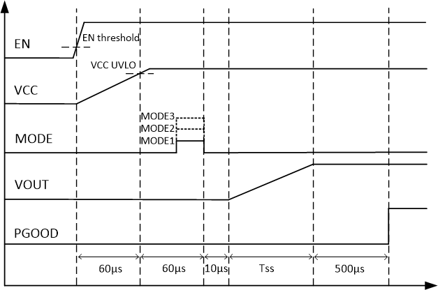
Figure 18 shows the typical start-up sequence of the device once the enable signal crosses the EN turn on threshold (VIN is higher then UVLO threshold). After the voltage on VCC crosses the rising UVLO threshold, it takes about 60 µs to read the mode setting .The output voltage starts ramping after 10 µs from the mode reading is done.
 Figure 18. Start-Up Sequence