ZHCSJZ2D August 2019 – April 2021 THS6222
PRODUCTION DATA
10.2 Wafer and Die Information
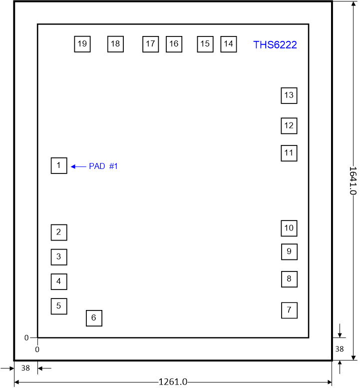
Table 10-1 lists wafer and bond pad information for the YSpackage.
Table 10-1 Wafer and Bond Pad Information
| WAFER BACKSIDE FINISH | WAFER THICKNESS | BACKSIDE POTENTIAL | BOND PAD METALLIZATION | BOND PAD DIMENSIONS (X × Y) |
|---|---|---|---|---|
| Silicon without backgrind | 25 mils | Must be connected to the lowest voltage potential on the die (generally VS–) | Al | 76.0 µm × 76.0 µm |

All dimensions are
in micrometers (µm).
Figure 10-1 Die DimensionsTable 10-2 lists the bond pad locations for the YS package. All dimensions are in micrometers (µm).
Table 10-2 Bond Pad Locations
| PAD NUMBER | PAD NAME | X MIN | Y MIN | X MAX | Y MAX | DESCRIPTION |
|---|---|---|---|---|---|---|
| 1 | D1_IN+ | 71.050 | 878.875 | 147.050 | 954.875 | Amplifier D1 noninverting input |
| 2 | D2_IN+ | 71.050 | 525.125 | 147.050 | 601.125 | Amplifier D2 noninverting input |
| 3 | DGND | 71.050 | 384.025 | 147.050 | 460.025 | Ground reference for bias control pins |
| 4 | IADJ | 71.050 | 267.025 | 147.050 | 343.025 | Bias current adjustment pin |
| 5 | VCM | 71.050 | 150.025 | 147.050 | 226.025 | Common-mode buffer output |
| 6 | VS– | 209.175 | 85.925 | 285.175 | 161.925 | Negative power-supply connection |
| 7 | VS+ | 1007.475 | 95.500 | 1083.475 | 171.500 | Positive power-supply connection |
| 8 | D2_OUT | 1007.475 | 222.500 | 1083.475 | 298.500 | Amplifier D2 output (must be used for D2 output) |
| 9 | D2_OUT (OPT) | 1007.475 | 369.900 | 1083.475 | 445.900 | Optional amplifier D2 output (can be left unconnected or connected to pad 8) |
| 10 | D2_IN– | 1007.475 | 487.375 | 1083.475 | 563.375 | Amplifier D2 inverting input |
| 11 | D1_IN– | 1007.450 | 919.375 | 1083.450 | 995.375 | Amplifier D1 inverting input |
| 12 | D1_OUT (OPT) | 1007.475 | 1034.100 | 1083.475 | 1110.100 | Optional amplifier D1 output (pad can be left unconnected or connected to pad 13) |
| 13 | D1_OUT | 1007.475 | 1181.500 | 1083.475 | 1257.500 | Amplifier D1 output (must be used for D1 output) |
| 14 | VS+ | 851.675 | 1417.950 | 927.675 | 1493.950 | Positive power-supply connection |
| 15 | VS+ | 718.900 | 1417.950 | 794.900 | 1493.950 | Positive power-supply connection |
| 16 | VS– | 557.375 | 1417.950 | 633.375 | 1493.950 | Negative power-supply connection |
| 17 | VS– | 424.600 | 1417.950 | 500.600 | 1493.950 | Negative power-supply connection |
| 18 | BIAS-1 | 293.075 | 1417.750 | 369.075 | 1493.750 | Bias mode parallel control, LSB |
| 19 | BIAS-2 | 159.250 | 1417.750 | 235.250 | 1493.750 | Bias mode parallel control, MSB |