ZHCSJZ6D June   2019  – December 2021 BQ25618 , BQ25619

PRODUCTION DATA  

  1. 特性
  2. 应用
  3. 说明
  4. Revision History
  5. 说明(续)
  6. Pin Configuration and Functions
  7. Specifications
    1. 7.1 Absolute Maximum Ratings
    2. 7.2 ESD Ratings
    3. 7.3 Recommended Operating Conditions
    4. 7.4 Thermal Information
    5. 7.5 Thermal Information
    6. 7.6 Electrical Characteristics
    7. 7.7 Timing Requirements
    8. 7.8 Typical Characteristics
  8. Detailed Description
    1. 8.1 Overview
    2. 8.2 Functional Block Diagram
    3. 8.3 Feature Description
      1. 8.3.1  Power-On-Reset (POR)
      2. 8.3.2  Device Power Up From Battery Without Input Source
      3. 8.3.3  Power Up From Input Source
        1. 8.3.3.1 Power Up REGN LDO
        2. 8.3.3.2 Poor Source Qualification
        3. 8.3.3.3 Input Source Type Detection (IINDPM Threshold)
          1. 8.3.3.3.1 PSEL Pins Sets Input Current Limit
        4. 8.3.3.4 Input Voltage Limit Threshold Setting (VINDPM Threshold)
        5. 8.3.3.5 Power Up Converter in Buck Mode
        6. 8.3.3.6 HIZ Mode with Adapter Present
      4. 8.3.4  Boost Mode Operation From Battery
      5. 8.3.5  Power Path Management
        1. 8.3.5.1 Narrow VDC Architecture
        2. 8.3.5.2 Dynamic Power Management
        3. 8.3.5.3 Supplement Mode
      6. 8.3.6  Battery Charging Management
        1. 8.3.6.1 Autonomous Charging Cycle
        2. 8.3.6.2 Battery Charging Profile
        3. 8.3.6.3 Charging Termination
        4. 8.3.6.4 Thermistor Qualification
          1. 8.3.6.4.1 JEITA Guideline Compliance During Charging Mode
          2. 8.3.6.4.2 Boost Mode Thermistor Monitor During Battery Discharge Mode
        5. 8.3.6.5 Charging Safety Timer
      7. 8.3.7  Ship Mode and QON Pin
        1. 8.3.7.1 BATFET Disable (Enter Ship Mode)
        2. 8.3.7.2 BATFET Enable (Exit Ship Mode)
        3. 8.3.7.3 BATFET Full System Reset
      8. 8.3.8  Status Outputs (STAT, INT , PMID_GOOD)
        1. 8.3.8.1 Power Good Indicator (PG_STAT Bit)
        2. 8.3.8.2 Charging Status Indicator (STAT)
        3. 8.3.8.3 Interrupt to Host (INT)
        4. 8.3.8.4 PMID Voltage Indicator (PMID_GOOD)
      9. 8.3.9  Protections
        1. 8.3.9.1 Voltage and Current Monitoring in Buck Mode
          1. 8.3.9.1.1 Input Overvoltage Protection (ACOV)
          2. 8.3.9.1.2 System Overvoltage Protection (SYSOVP)
        2. 8.3.9.2 Voltage and Current Monitoring in Boost Mode
          1. 8.3.9.2.1 Boost Mode Overvoltage Protection
          2. 8.3.9.2.2 PMID Overcurrent Protection
        3. 8.3.9.3 Thermal Regulation and Thermal Shutdown
          1. 8.3.9.3.1 Thermal Protection in Buck Mode
          2. 8.3.9.3.2 Thermal Protection in Boost Mode
        4. 8.3.9.4 Battery Protection
          1. 8.3.9.4.1 Battery Overvoltage Protection (BATOVP)
          2. 8.3.9.4.2 Battery Overdischarge Protection
          3. 8.3.9.4.3 System Overcurrent Protection
      10. 8.3.10 Serial Interface
        1. 8.3.10.1 Data Validity
        2. 8.3.10.2 START and STOP Conditions
        3. 8.3.10.3 Byte Format
        4. 8.3.10.4 Acknowledge (ACK) and Not Acknowledge (NACK)
        5. 8.3.10.5 Slave Address and Data Direction Bit
        6. 8.3.10.6 Single Read and Write
        7. 8.3.10.7 Multi-Read and Multi-Write
    4. 8.4 Device Functional Modes
      1. 8.4.1 Host Mode and Default Mode
    5. 8.5 Register Maps
  9. Application and Implementation
    1. 9.1 Application Information
    2. 9.2 Typical Application
      1. 9.2.1 Design Requirements
      2. 9.2.2 Detailed Design Procedure
        1. 9.2.2.1 Inductor Selection
        2. 9.2.2.2 Input Capacitor and Resistor
        3. 9.2.2.3 Output Capacitor
      3. 9.2.3 Application Curves
  10. 10Power Supply Recommendations
  11. 11Layout
    1. 11.1 Layout Guidelines
    2. 11.2 Layout Example
  12. 12Device and Documentation Support
    1. 12.1 Device Support
      1. 12.1.1 第三方米6体育平台手机版_好二三四免责声明
    2. 12.2 Documentation Support
      1. 12.2.1 Related Documentation
    3. 12.3 接收文档更新通知
    4. 12.4 支持资源
    5. 12.5 Trademarks
    6. 12.6 Electrostatic Discharge Caution
    7. 12.7 术语表
  13. 13Mechanical, Packaging, and Orderable Information

说明

BQ25618/619 将充电、升压转换器和电压保护功能集成在单个器件中。该器件为开关充电器提供了业界最低的终端电流,从而以最大电池容量为可穿戴设备充电。BQ25618/619 具有出色的低静态电流,可在运输模式下将电池泄漏降低至 6uA,从而节约电池电量,将器件的货架期延长一倍。BQ25619 采用 4x4 QFN 封装,以便于布局。BQ25618 采用 2.0x2.4mm2 WCSP 封装,以支持空间受限的设计。

器件信息
器件型号封装(1)封装尺寸(标称值)
BQ25618DSBGA (30)2.00mm × 2.40mm
BQ25619WQFN (24)4.00mm × 4.00mm
如需了解所有可用封装,请参阅数据表末尾的可订购米6体育平台手机版_好二三四附录。
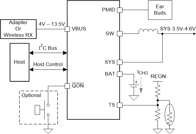
GUID-78685D67-5C44-4C54-AAAC-2EBE72F83AE6-low.gif简化版应用