ZHCSMI7A December 2020 – May 2021 TPS92633-Q1
PRODUCTION DATA
- 1 特性
- 2 应用
- 3 说明
- 4 Revision History
- 5 Pin Configuration and Functions
- 6 Specifications
-
7 Detailed Description
- 7.1 Overview
- 7.2 Functional Block Diagram
- 7.3
Feature Description
- 7.3.1 Power Supply (SUPPLY)
- 7.3.2 Enable and Shutdown (EN)
- 7.3.3 Reference Current (IREF)
- 7.3.4 Constant-Current Output and Setting (INx)
- 7.3.5 Analog Current Control (ICTRL)
- 7.3.6 Thermal Sharing Resistor (OUTx and RESx)
- 7.3.7 PWM Control (PWMx)
- 7.3.8 Supply Control
- 7.3.9
Diagnostics
- 7.3.9.1 IREF Short-to-GND Detection
- 7.3.9.2 IREF Open Detection
- 7.3.9.3 LED Short-to-GND Detection
- 7.3.9.4 LED Open-Circuit Detection
- 7.3.9.5 Single LED Short-Circuit Detection (SLS_REF)
- 7.3.9.6 LED Open-Circuit and Single LED Short-Circuit Detection Enable (DIAGEN)
- 7.3.9.7 Low Dropout Operation
- 7.3.9.8 Over-Temperature Protection
- 7.3.10 FAULT Bus Output With One-Fails–All-Fail
- 7.3.11 FAULT Table
- 7.3.12 LED Fault Summary
- 7.3.13 IO Pins Inner Connection
- 7.4 Device Functional Modes
- 8 Application and Implementation
- 9 Power Supply Recommendations
- 10Layout
- 11Device and Documentation Support
- 12Mechanical, Packaging, and Orderable Information
7.3.9.3 LED Short-to-GND Detection
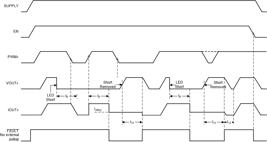
The TPS92633-Q1 device has LED short-to-GND detection. The LED short-to-GND detection monitors the output voltage when the output current is enabled. Once a short-to-GND LED failure is detected, the device turns off the faulty channel and retries automatically, regardless of the state of the PWM input. When the retry mechanism detects the removal of the LED short-to-GND fault, the device resumes to normal operation.
The TPS92633-Q1 monitors the V(OUTx) voltage and V(RESx) voltage of each channel and compares it with the internal reference voltage to detect a short-to-GND failure. When V(OUTx) or V(RESx) voltage falls below V(SG_th_falling) longer than the deglitch time of t(SG_deg), the device asserts the short-to-GND fault and pulls low the FAULT pin. During the deglitch time period, if V(OUTx) and V(RESx) rises above V(SG_th_rising), the timer is reset.
Once the TPS92633-Q1 has asserted a short-to-GND fault, the device turns off the faulty output channel and retries automatically with a small current. During retrying the device sources a small current I(Retry) from SUPPLY to OUT to pull up the LED loads continuously. Once auto-retry detects output voltage rising above V(SG_th_rising), it clears the short-to-GND fault and resumes to normal operation. Figure 7-7 illustrates the timing for LED short-circuit detection, protection, retry and recovery.
 Figure 7-7 LED Short-to-GND Detection and
Recovery Timing Diagram
Figure 7-7 LED Short-to-GND Detection and
Recovery Timing DiagramThe detailed information and value of each time period in Figure 7-7 is described in Timing Requirements.