ZHCSMW7B december 2020 – february 2023 TPS22950
PRODUCTION DATA
9.3.2 Current Limiting (TPS22950L)
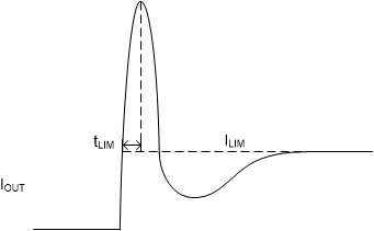
The TPS22950L responds to overcurrent conditions by limiting its output current to the current limit (ILIM) level after initially peaking its current at ILIM,PEAK. The behavior of the device is shown in Figure 9-3.
 Figure 9-3 Output Current Limit Behavior
When an overcurrent condition is detected, the device maintains a constant output current and reduces the output voltage accordingly. Two possible overload conditions can occur.
The first condition is when a short circuit or partial short circuit is present on the output and the ON pin is toggled high, turning the device on. The output voltage is held near zero potential with respect to ground and the TPS22950L ramps the output current to ILIM. The TPS22950L device limits the current to ILIM until the overload condition is removed. If the internal junction temperature of the device reaches thermal shutdown ,the device turns itself off. The device remains off until the junction temperature has lowered to TSDHYS, and the device turns itself back on. If thermal shutdown is not reached, the device waits for the load current to exceed the high current detection level (IHCD) for the tDEBOUNCE time and latch itself off. The FLT pin is pulled low, and the device is only able to turn on again by toggling the VIN or ON pins.
The second condition is when a short circuit, partial short circuit, or transient overload occurs after the device has been fully powered on. The device responds to the overcurrent condition within time tLIM (see Figure 9-4), and before this time the current is able to exceed ILIM. In the case of a fast transient, the current-sense amplifier is over-driven and momentarily disables the internal power FET. The current-sense amplifier recovers and limits the output current to ILIM. Similar to the previous case, the TPS22950L limits the current to ILIM until the overload condition is removed, the debounce time of 120 µs is reached, or the internal junction temperature of the device reaches thermal shutdown and begins thermally cycling on and off.
 Figure 9-4 Transient Current Limit Waveform