ZHCSMZ6B December   2020  – July 2022 ADC3664

PRODUCTION DATA  

  1. 特性
  2. 应用
  3. 说明
  4. Revision History
  5. Pin Configuration and Functions
  6. Specifications
    1. 6.1 Absolute Maximum Ratings
    2. 6.2 ESD Ratings
    3. 6.3 Recommended Operating Conditions
    4. 6.4 Thermal Information
    5. 6.5 Electrical Characteristics - Power Consumption
    6. 6.6 Electrical Characteristics - DC Specifications
    7. 6.7 Electrical Characteristics - AC Specifications
    8. 6.8 Timing Requirements
    9. 6.9 Typical Characteristics
  7. Parameter Measurement Information
  8. Detailed Description
    1. 8.1 Overview
    2. 8.2 Functional Block Diagram
    3. 8.3 Feature Description
      1. 8.3.1 Analog Input
        1. 8.3.1.1 Analog Input Bandwidth
        2. 8.3.1.2 Analog Front End Design
          1. 8.3.1.2.1 Sampling Glitch Filter Design
          2. 8.3.1.2.2 Analog Input Termination and DC Bias
            1. 8.3.1.2.2.1 AC-Coupling
            2. 8.3.1.2.2.2 DC-Coupling
      2. 8.3.2 Clock Input
        1. 8.3.2.1 Single Ended vs Differential Clock Input
      3. 8.3.3 Voltage Reference
        1. 8.3.3.1 Internal voltage reference
        2. 8.3.3.2 External voltage reference (VREF)
        3. 8.3.3.3 External voltage reference with internal buffer (REFBUF)
      4. 8.3.4 Digital Down Converter
        1. 8.3.4.1 DDC MUX
        2. 8.3.4.2 Digital Filter Operation
        3. 8.3.4.3 FS/4 Mixing with Real Output
        4. 8.3.4.4 Numerically Controlled Oscillator (NCO) and Digital Mixer
        5. 8.3.4.5 Decimation Filter
        6. 8.3.4.6 SYNC
        7. 8.3.4.7 Output Formatting with Decimation
      5. 8.3.5 Digital Interface
        1. 8.3.5.1 Output Formatter
        2. 8.3.5.2 Output Bit Mapper
        3. 8.3.5.3 Output Interface/Mode Configuration
          1. 8.3.5.3.1 Configuration Example
        4. 8.3.5.4 Output Data Format
      6. 8.3.6 Test Pattern
    4. 8.4 Device Functional Modes
      1. 8.4.1 Normal operation
      2. 8.4.2 Power Down Options
    5. 8.5 Programming
      1. 8.5.1 Configuration using PINs only
      2. 8.5.2 Configuration using the SPI interface
        1. 8.5.2.1 Register Write
        2. 8.5.2.2 Register Read
    6. 8.6 Register Maps
      1. 8.6.1 Detailed Register Description
  9. Application Information Disclaimer
    1. 9.1 Typical Application
      1. 9.1.1 Design Requirements
      2. 9.1.2 Detailed Design Procedure
        1. 9.1.2.1 Input Signal Path
        2. 9.1.2.2 Sampling Clock
        3. 9.1.2.3 Voltage Reference
      3. 9.1.3 Application Curves
    2. 9.2 Initialization Set Up
      1. 9.2.1 Register Initialization During Operation
    3. 9.3 Power Supply Recommendations
    4. 9.4 Layout
      1. 9.4.1 Layout Guidelines
      2. 9.4.2 Layout Example
  10. 10Device and Documentation Support
    1. 10.1 接收文档更新通知
    2. 10.2 支持资源
    3. 10.3 Trademarks
    4. 10.4 Electrostatic Discharge Caution
    5. 10.5 术语表
  11. 11Mechanical, Packaging, and Orderable Information

说明

ADC3664 器件是一款低噪声、超低功耗、14 位、125MSPS 高速双通道 ADC。该器件可实现超低噪声性能和 -156.9dBFS/Hz 的噪声频谱密度,还具有出色的线性度和动态范围。ADC3664 可提供中频采样支持,使器件适合各种应用。高速控制环路受益于低至一个时钟周期的低延迟。该 ADC 在 125MSPS 下的功耗仅为每通道 100mW,其功耗随采样率减小而迅速降低。

ADC3664 使用串行 LVDS (SLVDS) 接口输出数据,可更大限度减少数字互连的次数。该器件提供双通道、单通道和半通道选项。ADC3664 与 16 位分辨率 ADC 系列实现了引脚对引脚兼容。该器件支持 –40⁰C 至 +105⁰C 的工业级工作温度范围。

封装信息
器件型号封装(1)封装尺寸(标称值)
ADC3664VQFN (40)5.00 × 5.00mm
如需了解所有可用封装,请参阅数据表末尾的可订购米6体育平台手机版_好二三四附录。
表 3-1 器件比较
器件型号分辨率采样率
ADC366116 位10MSPS
ADC366216 位25MSPS
ADC366316 位65MSPS
ADC366414 位125MSPS
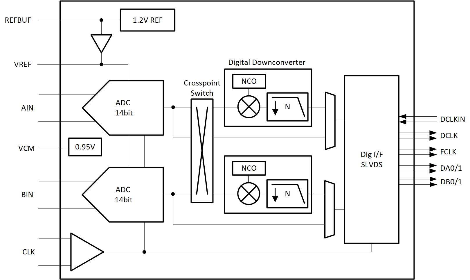
GUID-20200721-CA0I-1ZSN-3S1S-1WCJSDWZBKGR-low.gif简化版方框图