ZHCSN67N July   1997  – April 2021 SN55LVDS31 , SN65LVDS31 , SN65LVDS3487 , SN65LVDS9638

PRODUCTION DATA  

  1. 特性
  2. 应用
  3. 说明
  4. Revision History
  5. 说明(续)
  6. Pin Configuration and Functions
  7. Specifications
    1. 7.1 Absolute Maximum Ratings (1)
    2. 7.2 ESD Ratings
    3. 7.3 Recommended Operating Conditions
    4. 7.4 Thermal Information
    5. 7.5 Electrical Characteristics: SN55LVDS31
    6. 7.6 Electrical Characteristics: SN65LVDSxxxx
    7. 7.7 Switching Characteristics: SN55LVDS31
    8. 7.8 Switching Characteristics: SN65LVDSxxxx
    9. 7.9 Typical Characteristics
      1. 7.9.1 17
  8. Parameter Measurement Information
    1. 8.1 19
  9. Detailed Description
    1. 9.1 Overview
    2. 9.2 Functional Block Diagram
    3. 9.3 Feature Description
      1. 9.3.1 Driver Disabled Output
      2. 9.3.2 NC Pins
      3. 9.3.3 Unused Enable Pins
      4. 9.3.4 Driver Equivalent Schematics
    4. 9.4 Device Functional Modes
  10. 10Application and Implementation
    1. 10.1 Application Information
    2. 10.2 Typical Application
      1. 10.2.1 Point-to-Point Communications
        1. 10.2.1.1 Design Requirements
        2. 10.2.1.2 Detailed Design Procedure
          1. 10.2.1.2.1 Driver Supply Voltage
          2. 10.2.1.2.2 Driver Bypass Capacitance
          3. 10.2.1.2.3 Driver Output Voltage
          4. 10.2.1.2.4 Interconnecting Media
          5. 10.2.1.2.5 PCB Transmission Lines
          6. 10.2.1.2.6 Termination Resistor
          7. 10.2.1.2.7 Driver NC Pins
        3. 10.2.1.3 Application Curve
      2. 10.2.2 Multidrop Communications
        1. 10.2.2.1 Design Requirements
        2. 10.2.2.2 Detailed Design Procedure
          1. 10.2.2.2.1 Interconnecting Media
        3. 10.2.2.3 Application Curve
  11. 11Power Supply Recommendations
    1. 11.1 49
  12. 12Layout
    1. 12.1 Layout Guidelines
      1. 12.1.1 Microstrip vs. Stripline Topologies
      2. 12.1.2 Dielectric Type and Board Construction
      3. 12.1.3 Recommended Stack Layout
      4. 12.1.4 Separation Between Traces
      5. 12.1.5 Crosstalk and Ground Bounce Minimization
    2. 12.2 Layout Example
  13. 13Device and Documentation Support
    1. 13.1 Device Support
      1. 13.1.1 Other LVDS Products
    2. 13.2 Documentation Support
      1. 13.2.1 Related Information
      2. 13.2.2 接收文档更新通知
      3. 13.2.3 Related Links
    3. 13.3 支持资源
    4. 13.4 Trademarks
    5. 13.5 静电放电警告
    6. 13.6 术语表
  14. 14Mechanical, Packaging, and Orderable Information

说明

SN55LVDS31、SN65LVDS31、SN65LVDS3487 和 SN65LVDS9638 器件是差分线路驱动器,可实现低电压差分信号 (LVDS) 的电气特性。这个信号传输技术降低了 5V 差分标准电平(例如 TIA/EIA-422B)的输出电压电平,从而减少了功耗、增加了开关速度、并可实现 3.3V 电源轨供电下的运行。启用后,四个电流模式驱动器中的任何一个都将向 100Ω 负载提供最小 247mV 的差分输出电压幅度。

器件信息(1)
器件型号封装封装尺寸(标称值)
SN55LVDS31LCCC (20)8.89mm × 8.89mm
CDIP (16)19.56mm × 6.92mm
CFP (16)10.30mm × 6.73mm
SN65LVDS31SOIC (16)9.90mm x 3.91mm
SOP (16)10.30mm × 5.30mm
TSSOP (16)5.00mm × 4.40mm
SN65LVDS3487SOIC (16)9.90mm x 3.91mm
TSSOP (16)5.00mm × 4.40mm
SN65LVDS9638SOIC (8)4.90mm × 3.91mm
VSSOP (8)3.00mm × 3.00mm
HVSSOP (8)3.00mm × 3.00mm
如需了解所有可用封装,请参阅数据表末尾的可订购米6体育平台手机版_好二三四附录。
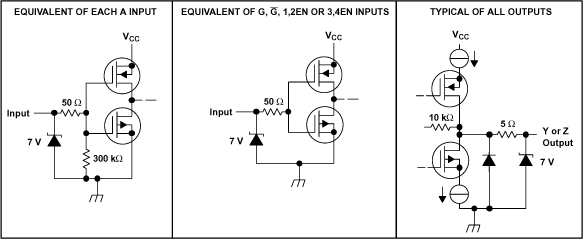
GUID-555D6387-E6C5-4F54-9C39-26E7F8769D18-low.gif等效输入和输出原理图