ZHCSNM5C november 2020 – august 2023 UCC25800-Q1
PRODUCTION DATA
- 1
- 1 特性
- 2 应用
- 3 说明
- 4 Revision History
- 5 Device Comparison Table
- 6 Pin Configuration and Functions
- 7 Specifications
- 8 Detailed Description
- 9 Application and Implementation
- 10Power Supply Recommendations
- 11Layout
- 12Device and Documentation Support
- 13Mechanical, Packaging, and Orderable Information
8.3.5.1 Overcurrent Protection
The UCC25800-Q1 transformer driver has two levels of overcurrent protection (OCP).
- The first level (OCP1) triggers if the current through the low-side
MOSFET exceeds programmed threshold IOCP during its on-time in each switching
cycle for 2.1 ms. Refer to OCP Threshold Setting for OCP1 threshold programming details.
- OCP1 detection is based on only the low-side MOSFET current, when the SW pin current flows into the SW pin
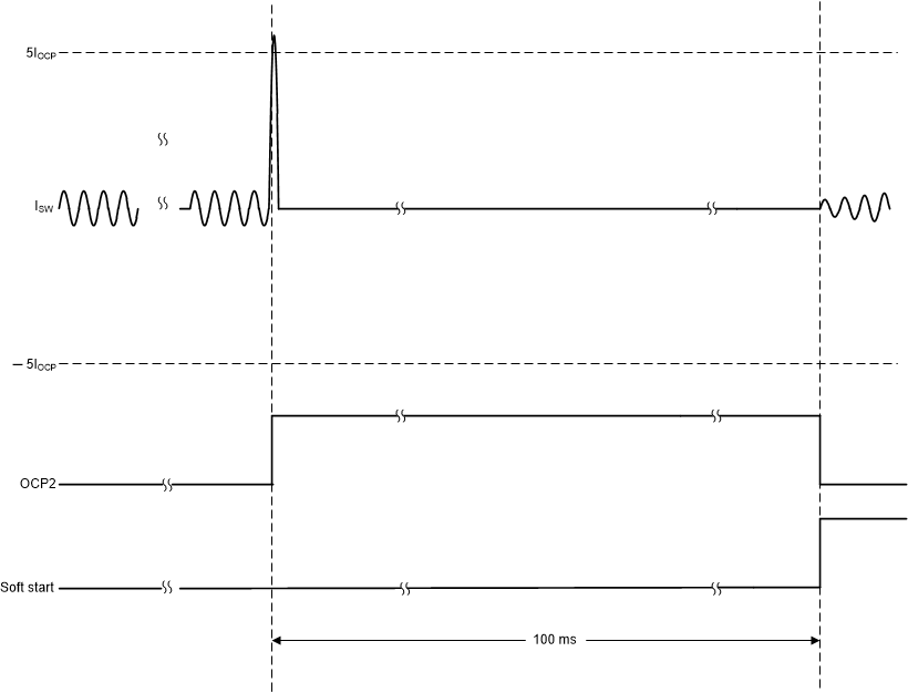
- The second level (OCP2) triggers if the current in either the
high-side or low-side MOSFET exceeds 5 × IOCP for 100 ns.
- The OCP2 threshold is set significantly above OCP1 threshold to allow the unit to cope with heavy load surges for a short duration, or during the start-up to charge the large output capacitor. If OCP2 is exceeded, it indicates that there is a serious fault in the system. OCP2 tracks OCP1 so that events like output overload can still trip OCP2, even if the current limit is set well below the maximum current limit of the transformer driver.
- During soft-start
- The OCP1 is disabled
- The OCP2 threshold is fixed at its maximum value of 5 A
- After soft-start
- OCP1 is enabled, with the threshold IOCP equal to the programmed value
- OCP2 threshold becomes 5 times of the programmed IOCP level.
- The OCP1 overcurrent timer is implemented as an up-down counter to
ensure that the repetitive short over-current events as well as a sustained 2.1-ms over
current trigger the OCP.
- OCP1 overcurrent timer counts up if the SW current crosses IOCP for longer than 100 ns in each switching cycle
- OCP1 overcurrent timer counts down if the SW current does not cross IOCP for longer than 100 ns in the entire switching cycle
- The internal counter for OCP1 overcurrent timer counts up in 2.1 ms from 0 to the trip threshold and counts down in 180 ms from the trip threshold down to 0.
- OCP2 detection has an analog filter which filters out pulses of less than 100 ns.
The transformer driver imposes a restart time of 100 ms before restarting from overcurrent protection to maintain the RMS current in the transformer driver below its limit. The OCP behaviors are illustrated in Figure 8-10 and Figure 8-11.
 Figure 8-10 OCP1 protection and recovery behavior
 Figure 8-11 OCP2 protection and recovery behavior