ZHCSWR1H December   2009  – July 2024 DRV8412

PRODUCTION DATA  

  1.   1
  2. 1特性
  3. 2应用
  4. 3说明
  5. 4Pin Configuration and Functions
  6. 5Specifications
    1. 5.1 Absolute Maximum Ratings
    2. 5.2 ESD Ratings
    3. 5.3 Recommended Operating Conditions
    4. 5.4 Thermal Information
    5. 5.5 Package Heat Dissipation Ratings
    6. 5.6 Package Power Deratings (DRV8412) #GUID-2A6DB468-D895-404F-A2E6-05A442AE2834/SLES2429141
    7. 5.7 Electrical Characteristics
    8. 5.8 Typical Characteristics
  7. 6Detailed Description
    1. 6.1 Overview
    2. 6.2 Functional Block Diagram
    3. 6.3 Feature Description
      1. 6.3.1 Error Reporting
      2. 6.3.2 Device Protection System
        1. 6.3.2.1 Bootstrap Capacitor Undervoltage Protection
        2. 6.3.2.2 Overcurrent (OC) Protection
        3. 6.3.2.3 Overtemperature Protection
        4. 6.3.2.4 Undervoltage Protection (UVP) and Power-On Reset (POR)
      3. 6.3.3 Device Reset
    4. 6.4 Device Functional Modes
  8.   Application and Implementation
    1. 7.1 Application Information
    2. 7.2 Typical Applications
      1. 7.2.1 Full Bridge Mode Operation
        1. 7.2.1.1 Design Requirements
        2. 7.2.1.2 Detailed Design Procedure
          1. 7.2.1.2.1 Motor Voltage
          2. 7.2.1.2.2 Current Requirement of 12V Power Supply
          3. 7.2.1.2.3 Voltage of Decoupling Capacitor
          4. 7.2.1.2.4 Overcurrent Threshold
          5. 7.2.1.2.5 Sense Resistor
        3. 7.2.1.3 Application Curves
      2. 7.2.2 Parallel Full Bridge Mode Operation
      3. 7.2.3 Stepper Motor Operation
      4. 7.2.4 TEC Driver
      5. 7.2.5 LED Lighting Driver
    3. 7.3 Power Supply Recommendations
      1. 7.3.1 Bulk Capacitance
      2. 7.3.2 Power Supplies
      3. 7.3.3 System Power-Up and Power-Down Sequence
        1. 7.3.3.1 Powering Up
        2. 7.3.3.2 Powering Down
      4. 7.3.4 System Design Recommendations
        1. 7.3.4.1 VREG Pin
        2. 7.3.4.2 VDD Pin
        3. 7.3.4.3 OTW Pin
        4. 7.3.4.4 Mode Select Pin
        5. 7.3.4.5 Parallel Mode Operation
        6. 7.3.4.6 TEC Driver Application
    4. 7.4 Layout
      1. 7.4.1 Layout Guidelines
        1. 7.4.1.1 PCB Material Recommendation
        2. 7.4.1.2 Ground Plane
        3. 7.4.1.3 Decoupling Capacitor
        4. 7.4.1.4 AGND
      2. 7.4.2 Layout Example
        1. 7.4.2.1 Current Shunt Resistor
      3. 7.4.3 Thermal Considerations
        1. 7.4.3.1 DRV8412 Thermal Via Design Recommendation
  9. 7Device and Documentation Support
    1. 7.1 接收文档更新通知
    2. 7.2 支持资源
    3. 7.3 Trademarks
    4. 7.4 静电放电警告
    5. 7.5 术语表
  10. 8Revision History
  11. 9Mechanical, Packaging, and Orderable Information

说明

DRV841x2 是具有先进保护系统的高性能、集成式双路全桥电机驱动器。

得益于 H 桥 MOSFET 的低 RDS(on) 和智能栅极驱动设计,这些电机驱动器的效率可高达 97%。这种高效率支持使用更小的电源和散热器,使得此类器件非常适合节能应用。

DRV841x2 需要两个电源,一个为 12V,用于 GVDD 和 VDD,另外一个可高达 50V,用于 PVDD。DRV841x2 可以在高达 500kHz 的开关频率下运行,同时仍保持精确控制和高效率。这些器件还具有创新的保护系统,可保护器件免受可能损坏系统的各种故障条件的影响。这些保护是短路保护、过流保护、欠压保护和两级过热保护。DRV841x2 有一个限流电路,此电路可在诸如电机启动等负载瞬态期间防止器件过流关断。一个可编程过流检测器可实现可调电流限值和保护级别,以满足不同的电机要求。

DRV841x2 的每个半桥都有独特的独立电源和接地引脚。借助这些引脚,可以通过外部分流电阻提供电流测量,并支持具有不同电源电压要求的多个电机。

封装信息
器件型号封装(1)封装尺寸(2)
DRV8412HTSSOP (44)14mm x 8.1mm
DRV8432HSSOP (36)15.9mm x 14.2mm
有关更多信息,请参阅节 9
封装尺寸(长 × 宽)为标称值,并包括引脚(如适用)。
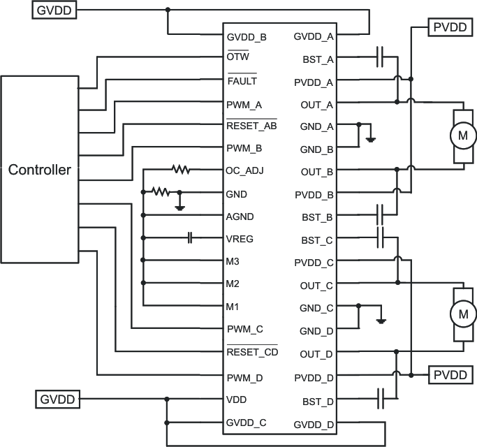
DRV8412 DRV8432 简化版应用示意图简化版应用示意图