ZHCSWR1H
December 2009 – July 2024
DRV8412
PRODUCTION DATA
1
1
特性
2
应用
3
说明
4
Pin Configuration and Functions
5
Specifications
5.1
Absolute Maximum Ratings
5.2
ESD Ratings
5.3
Recommended Operating Conditions
5.4
Thermal Information
5.5
Package Heat Dissipation Ratings
5.6
Package Power Deratings (DRV8412) #GUID-2A6DB468-D895-404F-A2E6-05A442AE2834/SLES2429141
5.7
Electrical Characteristics
5.8
Typical Characteristics
6
Detailed Description
6.1
Overview
6.2
Functional Block Diagram
6.3
Feature Description
6.3.1
Error Reporting
6.3.2
Device Protection System
6.3.2.1
Bootstrap Capacitor Undervoltage Protection
6.3.2.2
Overcurrent (OC) Protection
6.3.2.3
Overtemperature Protection
6.3.2.4
Undervoltage Protection (UVP) and Power-On Reset (POR)
6.3.3
Device Reset
6.4
Device Functional Modes
Application and Implementation
7.1
Application Information
7.2
Typical Applications
7.2.1
Full Bridge Mode Operation
7.2.1.1
Design Requirements
7.2.1.2
Detailed Design Procedure
7.2.1.2.1
Motor Voltage
7.2.1.2.2
Current Requirement of 12V Power Supply
7.2.1.2.3
Voltage of Decoupling Capacitor
7.2.1.2.4
Overcurrent Threshold
7.2.1.2.5
Sense Resistor
7.2.1.3
Application Curves
7.2.2
Parallel Full Bridge Mode Operation
7.2.3
Stepper Motor Operation
7.2.4
TEC Driver
7.2.5
LED Lighting Driver
7.3
Power Supply Recommendations
7.3.1
Bulk Capacitance
7.3.2
Power Supplies
7.3.3
System Power-Up and Power-Down Sequence
7.3.3.1
Powering Up
7.3.3.2
Powering Down
7.3.4
System Design Recommendations
7.3.4.1
VREG Pin
7.3.4.2
VDD Pin
7.3.4.3
OTW Pin
7.3.4.4
Mode Select Pin
7.3.4.5
Parallel Mode Operation
7.3.4.6
TEC Driver Application
7.4
Layout
7.4.1
Layout Guidelines
7.4.1.1
PCB Material Recommendation
7.4.1.2
Ground Plane
7.4.1.3
Decoupling Capacitor
7.4.1.4
AGND
7.4.2
Layout Example
7.4.2.1
Current Shunt Resistor
7.4.3
Thermal Considerations
7.4.3.1
DRV8412 Thermal Via Design Recommendation
7
Device and Documentation Support
7.1
接收文档更新通知
7.2
支持资源
7.3
Trademarks
7.4
静电放电警告
7.5
术语表
8
Revision History
9
Mechanical, Packaging, and Orderable Information
7.2.3
Stepper Motor Operation
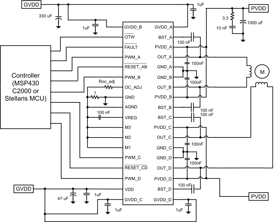
Figure 7-9
Application Diagram Example for Stepper Motor Operation Schematic
千亿体育app官网登录(中国)官方网站IOS/安卓通用版/手机APP
|
米乐app下载官网(中国)|ios|Android/通用版APP最新版
|
米乐|米乐·M6(中国大陆)官方网站
|
千亿体育登陆地址
|
华体会体育(中国)HTH·官方网站
|
千赢qy国际_全站最新版千赢qy国际V6.2.14安卓/IOS下载
|
18新利网v1.2.5|中国官方网站
|
bob电竞真人(中国官网)安卓/ios苹果/电脑版【1.97.95版下载】
|
千亿体育app官方下载(中国)官方网站IOS/安卓/手机APP下载安装
|