ZHCU710 October 2019
2.4.1 Super Capacitor Linear Charger Circuit
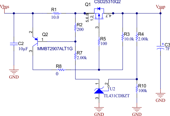
Figure 2 shows the super capacitor linear charger circuit of TIDA-050033. A linear charger is implemented in this reference design. The benefits of the linear charger are simplicity and low cost. TI’s P-Channel MOSFET CSD25310Q2 (Q1) is the core of the discrete charger circuit. Since a P-Channel MOSFET remains off when the gate-source voltage is zero and turns on when the voltage is negative. A low cost PNP device Q2 is used to drive Q1. The current sense resistor R1 connected to Q2 defines the charging current, which is around 60mA. The adjustable shunt regulator TL431 limits the charging voltage to 2.5 V. The circuit behaves like a linear regulator. Nearly all of the losses are converted to heat, so the power dissipation must be kept below the thermal limit. The current charging time is about 330 seconds for a super capacitor of 7 F.
