ZHCU734A January 2017 – March 2020
3.2.3.1.2.6 Run the Code
- Run the code by using the <F8> key or the Run button on the toolbar.
- As this is an open-loop test (no voltage loop), care must be taken not to use too small a load to avoid accidental high output voltages. Use a load of 5A at the 12-V output.
- Set the 400-V DC supply to output 300 V (this value is lower than the 370-V, low-end limit for the reason mentioned in the previous step). Set the power supply current limit to an appropriate level for this test. Now turn ON this 300-V power supply.
- In the Expressions Window set LLC_startFlag = 1. The converter operation should start with the default LLC_periodSet_pu value resulting in approximately 350-kHz switching frequency..
- Verify that all of the sensed values are updating in the expressions window: LLC_vPri_Volts, LLC_iPri_PH1_Amps, LLC_iPri_PH2_Amps, LLC_iSec_Amps.
- The LLC_periodRef_debug_pu value may be changed between 0.57 and 1.00. As this value is increased the switching frequency decreases, which results in a higher energy delivered to the load. In open loop this results in an increase in output voltage, which should not be allowed to exceed board capabilities.
- Verify that as the LLC_periodRef_debug_pu value is changed, the sense values reflect those changes. The secondary voltage should increase / decrease, and the primary and secondary currents should change accordingly.
- The LLC_dutySet_PH1_debug_pu, and LLC_dutySet_PH2_debug_pu variables are initialized to 0.99, but they may be set to values between 0.05 and 0.99. An oscilloscope may be used to observe the changing duty cycle for the switch waveforms.
- If desired, the SFRA tool may now be used to look at the frequency response of the plant.
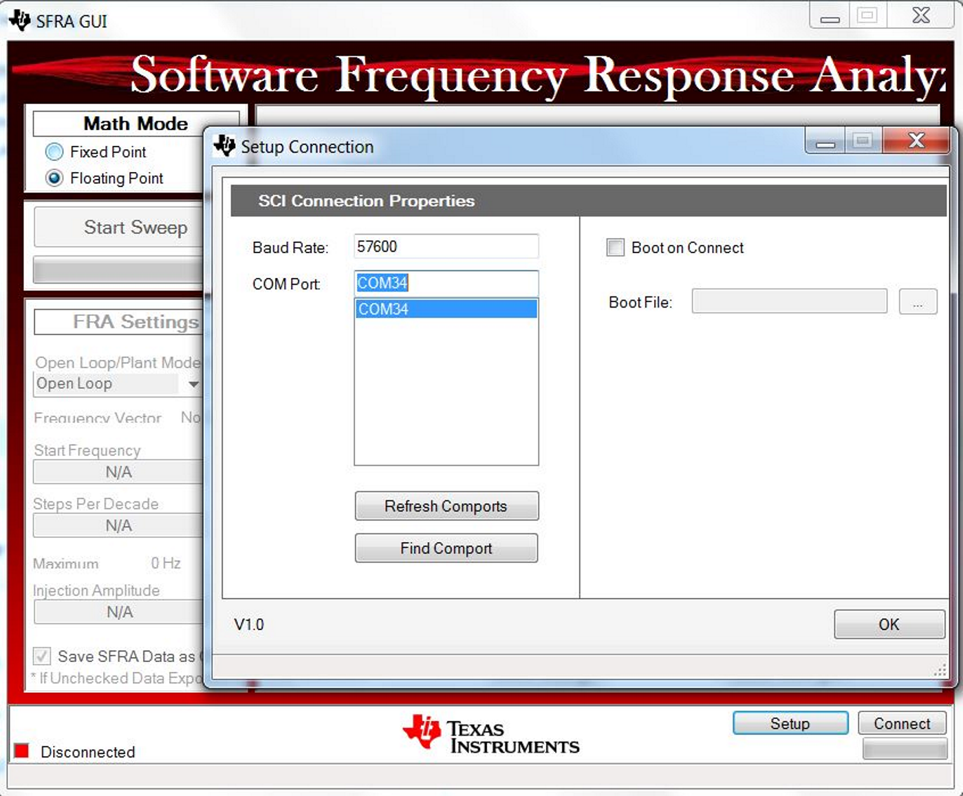
- To do this click on main.syscfg file and open SFRA. Click on setup connection and select the appropriate COM port. Make sure that the baud rate is set to 57600 and that Boot on Connect is unchecked. Click OK.
- Select Floating Point math.
- Click Connect on the SFRA GUI. Once the GUI is connected, click on Start Sweep. SFRA will start applying different frequencies and collecting the response for frequency analysis.
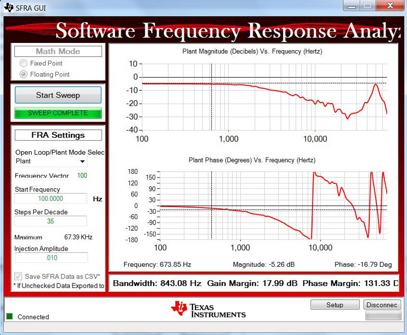
- Once the frequency sweep is complete, the response will be displayed on the SFRA GUI, as shown in Figure 26.
- Close the SFRA GUI.
- Turn OFF the 300-V DC power supply.
- Fully halting the MCU when in real-time mode is a two-step process. First, halt the processor by using the Suspend button (
 ) on the toolbar or by using Run → Suspend. Click
  button again to take the MCU out of real-time mode and then reset the MCU (Run → Reset → CPU Reset).
 - CCS may be left running for the next lab or optionally close CCS.
End of exercise.

