ZHCU737A June 2016 – May 2019 TPS3828
5.2.2 PLC Only Node Setup
This section covers how to run the PLC only node as a mini-DC with GUI.
- Connect the PLC only node to the PC and open the intermediate GUI.
- Set a unique long address for each device by using Set System Config.
- Start a device as a mini-DC by selecting Functions → Start Base Node.
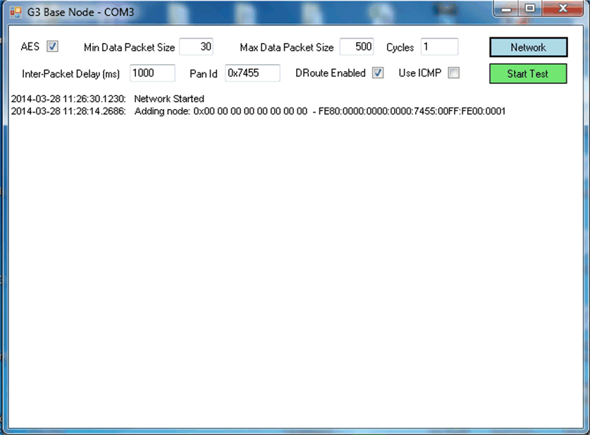
- In the pop-up window of the G3 Base Node, click Start Network.
- Once the hybrid wireless M-Bus/PLC node is joined, the IPv6 information for the joined node will be available.
- Set the Max Data Packet Size to 184 due to the maximum size limitation of the wireless M-Bus specification. Then, start data echo-back testing by selecting Start Test.
Figure 17. Set System Configuration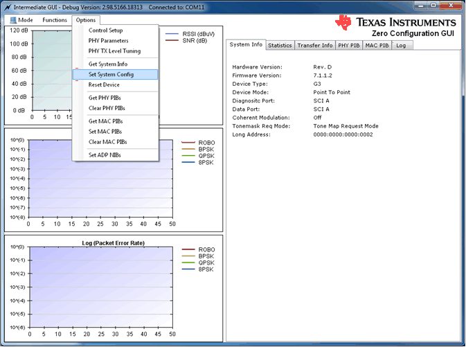

Figure 18. G3-PLC System Configuration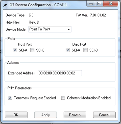

Figure 19. Start Base Node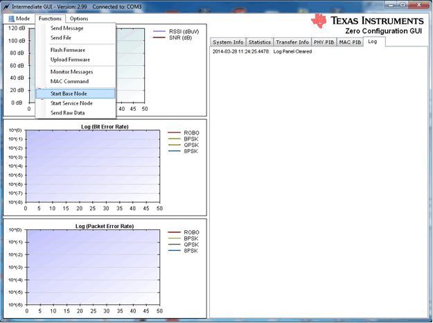

Figure 20. G3-PLC Base Node Window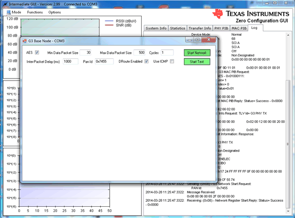

Figure 21. Joining Node Information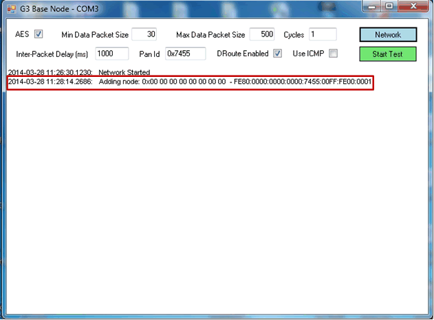

Figure 22. Start Data Echo-Back Test