ZHCU740 April 2020
3 Layout
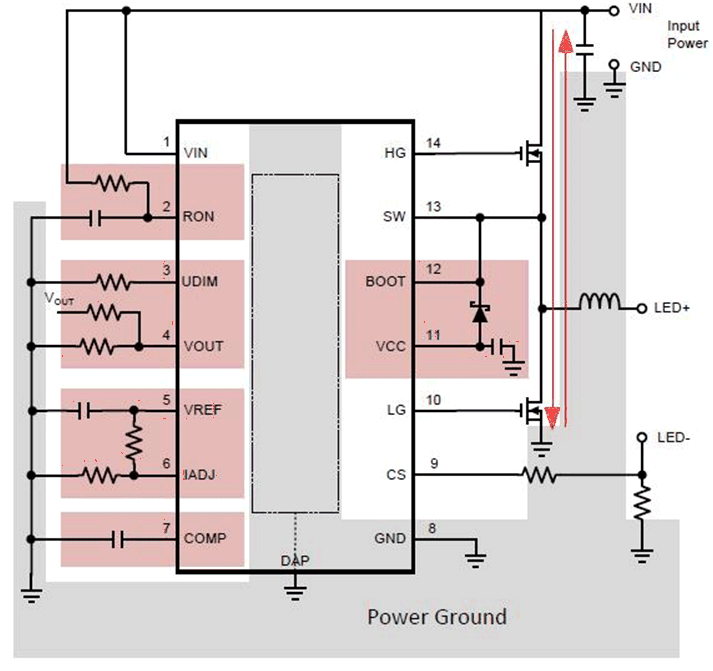
Figure 14 shows the layout guidelines taken from the TPS92641 Synchronous Buck Controllers for Precision Dimming LED Drivers data sheet.
Discontinuous currents are the most likely to generate EMI, therefore take care when routing these paths. The main path for discontinuous current in the TPS92640 and TPS92641 buck converters contain the input capacitor (CIN), the low side MOSFET (QLS), and the high side MOSFET (QHS). This loop should be kept as small as possible and the connections between all three components should be short and thick to minimize parasitic inductance. In particular, the switch node (where L, QLS, and QHS connect) should be just large enough to connect the components without excessive heating from the current it carries. The current sense trace (CS pin) should be run along with a ground plane or have differential traces run for CS and ground.
In some applications, the LED or LED array can be far away (several inches or more) from the circuit, or on a separate PCB connected by a wiring harness. When an output capacitor is used and the LED array is large or separated from the rest of the converter, the output capacitor should be placed close to the LEDs to reduce the effects of parasitic inductance on the AC impedance of the capacitor.
